Open the Properties Grid panel, if not already opened.
In the model space, select one or more tendons that you want to change the properties for.
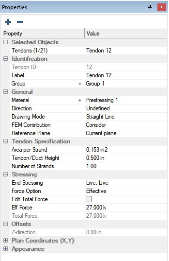
The properties that can be modified will display in the properties grid as shown in the following image.

Modify the properties to match the criteria for your design. The different properties that can be set within the Properties Grid are outlined below.
The identification section of the tendon properties includes the Tendon ID, Label and Group properties. These properties help the program and the user identify and group components.

The following table provides a description of the properties that can be set.
|
|
Description |
|---|---|
|
Identification: |
|
|
Tendon ID |
Tendon ID displays the internal tendon id used by the program to differentiate tendons. The tendon ID can not be modified by the user. |
|
Label |
Label allows you to modify the tendon label of the currently selected tendon(s). |
|
Group |
Group allows you to set the group the tendons are assigned to as defined in the Visibility>Group Library dialog for display purposes. |
The General section of the tendon properties is where the user can set general properties including the tendon material, drawing mode, and whether the tendon should be considered or disregarded from the analysis of the model.

The following table provides a description of the properties that can be set.
|
|
Description |
|---|---|
|
General: |
|
|
Material |
Material allows the user to select and assign the post-tensioning material for the tendon. Click the + icon to open the prestressing material dialog window to define or modify tendon materials. |
|
Direction |
Direction allows the user to define the tendon direction. The available options are:
The user can then use the visibility grid to turn on and off groups of tendons based on the direction property. |
|
Drawing Mode |
Drawing Mode allows the user to select the mode of the tendon. The available options are:
|
|
FEM Contribution |
FEM Contribution allows the user to either "consider" or "disregard" the tendon from the FEM Analysis. |
|
Connect to ramp below |
Check if the tendon to be modeled should be located in the ramp component when a slab and ramp are overlapping. Uncheck if the tendon should stay at the slab level. |
|
Reference Plane |
Reference Plane allows the user to change the reference plane the tendon is assigned to. |
The Tendon Specification section of the tendon properties is where the user can set the area per strand, tendon/duct height, and number of strands in the tendon.

The following table provides a description of the properties that can be set.
|
|
Description |
|---|---|
|
Tendon Specification: |
|
|
Area per Strand |
Area per Strand allows the user to modify the strand area of the tendon. |
|
Tendon/Duct Height |
Tendon/Duct Height allows the user to define the diameter of the tendon (unbonded) or the diameter of duct (bonded). |
|
Number of Strands |
Number of Strands allows the user to define the number of strands per tendon. For example, if using a 7-wire strand unbonded cable and you need two cables the number of strands would be set to 2. |
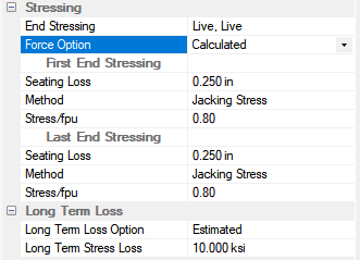
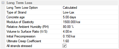
The Stressing section of the Tendon Properties allows the user to define the stressing ends and calculated or effective force option for the tendons. When the Force Option of the Stressing section is set to Effective the user can modify the total and/or effective Force of the modeled tendon. When the Force Option of the Stressing section is set to Calculated the user can enter seating loss and long term loss properties of the tendon used in calculating the friction. elongation. and long-term loss values. Other properties related to the loss calculations can be set per tendon span in the Shape/System/Friction tab of the tendon properties dialog. Please see the Shape/System/Friction section of this help menu for more information.
Force Option set to Effective:

Force Option set to Calculated:

The following table provides a description of the properties that can be set.
|
|
Description | ||||||||||||||||||||||||||||||||||||||||||||||||||||||||||||||||||||||||
|---|---|---|---|---|---|---|---|---|---|---|---|---|---|---|---|---|---|---|---|---|---|---|---|---|---|---|---|---|---|---|---|---|---|---|---|---|---|---|---|---|---|---|---|---|---|---|---|---|---|---|---|---|---|---|---|---|---|---|---|---|---|---|---|---|---|---|---|---|---|---|---|---|---|
|
Stressing: |
|||||||||||||||||||||||||||||||||||||||||||||||||||||||||||||||||||||||||
|
End Stressing |
End Stressing allows the user to set the dead and live ends of the tendon. Available options are:
The input is first end, second end respectively. For the effective force method this is only used as a graphical display of stressing and live ends. |
||||||||||||||||||||||||||||||||||||||||||||||||||||||||||||||||||||||||
|
Force Option |
Force Option allows the user to set the force used for the tendon. The available options and the properties they unlock are as follows:
|
||||||||||||||||||||||||||||||||||||||||||||||||||||||||||||||||||||||||
The Offsets section of the tendon properties is not used and can not be accessed. The location of the tendon is referenced from the slab/beam/ramp the tendon is modeled in.

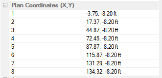
The Plan Coordinates (X, Y) section of the tendon properties lists the coordinates of the verticies (end/high points) along the tendon. Modify the coordinates to modify the location of the tendon on plan.

In the Appearance section of the tendon properties the user can modify the thickness of the tendon and it's text, the drawing layer the tendon is located on and the color of the tendon.

|
|
Description |
|---|---|
|
Appearance: |
|
|
Layer |
Layer allows the user to modify the drawing layer the tendon is on. Pick the new layer from the drop down list. |
|
Line Thickness |
Line Thickness allows the user to increase or decrease the line thickness of the tendon on plan. |
|
Text Thickness |
Text Thickness allows the user to increase or decrease the thickness of the tendon fonts. |
|
Outline Color |
Outline Color allows the user to modify the color of the tendons on screen. Choose the new color from the color palette.
|
Repeat steps 2 - 4, until all tendons have the correct properties set for the design.


