Boundary Conditions
Boundary Conditions define how the model is externally constrained.
All models must be attached to some external point or points of support. You may define these points of support as completely restrained or as
partially restrained with a Spring. You can
also define a spring support that has stiffness in only one direction
with tension-only or compression-only springs.
For additional advice on this topic, please see the RISA Tips & Tricks webpage at risa.com/post/support. Type in Search keywords: Boundary Conditions.
Creating and Modifying Boundary Conditions
There are a number of ways to create or modify boundary conditions. You
may view and edit the data in the Boundary Conditions
Spreadsheet, you may double-click a joint to view and edit its properties,
or you can use the Modify Boundaries tool to graphically assign or modify a possibly
large selection of boundary conditions.
Modify Boundary Conditions for
Joints
The graphical Modify Boundary tool discussed here lets you specify and modify boundary conditions graphically. To use this, you will typically
specify the new boundary condition, then select the joints that you want
to assign or modify.
You can modify or assign joints one at a time by selecting the
Apply by Clicking/Boxing option and then click on the joints you wish to
modify. You may also modify or assign entire selections of joints by selecting
the joints first and then use the Apply to All Selected option.
The parameters shown below are the same as those on the Boundary Conditions
Spreadsheet and are described in Boundary Condition
Options. Use the arrow buttons to select the boundary condition.
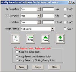
The Use? check boxes next to the data fields indicate whether
the particular parameter will be used or not when the modification is
applied. If the box next to a field is checked, that parameter will
be applied to any selected joints If the box is NOT checked, the
parameter will NOT be applied, even if a value is entered in the field.
This lets you easily change one or two parameters on joints without affecting
all the rest of the parameters.
-
If
there is not a model view already open, click  on the RISA Toolbar
to open a new view and click
on the RISA Toolbar
to open a new view and click  to turn on
the Drawing Toolbar if it is not already displayed.
to turn on
the Drawing Toolbar if it is not already displayed.
-
Click
the  Boundary Conditions button on the Home tab and define the boundary condition. Check the Use? Box for the items to apply.
-
You
may apply the boundary condition by choosing joints on the fly or apply
it to a selection of joints.
To choose joints on the fly, choose Apply Entries
by Clicking/Boxing Joints and click Apply. Click/Box
the joints with the left mouse button.
To apply the boundary condition to a selection of joints,
choose Apply Entries
to All Selected Joints and click Apply.
Note
- To apply more boundaries
with different conditions, press CTRL-D to recall the Boundary Conditions Dialog.
- You may also view
and edit boundary conditions by double-clicking on a joint.
- You may also specify
or edit boundary conditions in the Boundary Conditions Spreadsheet.
- You may undo any
mistakes by clicking the Undo
 button.
Boundary Conditions Spreadsheet
The Boundary Conditions Spreadsheet records the boundaries for
the joints and may be accessed by selecting Boundary Conditions on
the Spreadsheets Menu.
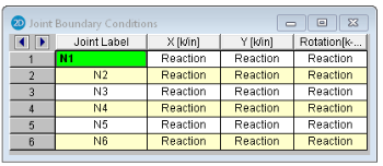
The Joint Label column contains the label of the joint that is restrained.
The remaining columns record the boundary conditions that apply to the
joint. There are three degrees of freedom for
each joint (2 translation, 1
rotation), so there are three columns for degrees of freedom.
The boundary conditions are entered in these remaining columns by selecting
the cell, clicking  and choosing from
the boundary options. You may also type them in directly.
and choosing from
the boundary options. You may also type them in directly.
Boundary Condition Options
Free joints have no restraint in any of the degrees of freedom and need
not be listed on the Boundary Conditions Spreadsheet. The following
are the valid boundary condition options that may be used for the three
degrees of freedom.
Note
- Models
that contain compression-only or tension-only springs must be iterated until
the solution converges. Convergence is achieved when no more load
reversals are detected in the springs. During the iteration process,
each spring is checked, and if any springs are turned off (or back
on), the stiffness matrix is rebuilt and model is resolved.
This can take quite a bit longer than a regular static solution.
- With this iteration procedure it is possible to run into a phenomenon known as "clapping". This occurs when a compression-only spring keeps going between a tension force present (where the spring is removed) to a compression force present (where the spring is re-added). This can be somewhat common in non-linear solutions. If you run into this phenomenon, you may see the program give Error 1162. The fix is to very slightly adjust either the loading or the spring/element stiffness to get the offending spring out of the range where it can bounce back and forth. Another option would be to move the location of the soil spring slightly so it's not right at an inflection boundary.
- You can enter the
first letter of the option ("R" for Reaction, "S"
for Spring, etc.) rather than typing out the entire code. RISA-2D fills in the rest automatically. The exception
is the Tether entry, where the full word does have to be entered. After Tether, the primaryjoint needs to be entered (for example, Tether N2)
Boundary Condition at ALL Joints
The entry "ALL" may be entered in the Joint Label
field. The boundary conditions entered on this line will be applied
to ALL the joints not otherwise listed. This is useful if you should
want to lock certain directions of movement for all or most of the joints.
Note
- If a joint is explicitly
listed with boundary conditions, those boundary conditions override the
"ALL" conditions for all 3 directions. The "ALL"
specified boundary codes apply only to those joints NOT otherwise listed
on the Boundary Conditions Spreadsheet.
- When using the "ALL" command, boundary conditions are no longer graphically displayed.
Reaction Boundary Condition
The "R" code, for Reaction, specifies full restraint for
the indicated direction. No movement will be allowed in the indicated
direction for this joint. Furthermore, the reaction will be calculated
at this joint, for this direction.
Fixed Boundary Condition
The "F" code, for Fixed, specifies full restraint for the
joint in the indicated direction. The difference between "Fixed"
and "Reaction" is that for the "Fixed" code, no reaction
is calculated. The "Fixed" condition actually removes
the degree of freedom from the solution, which is why the reaction value
is not available. If you aren't interested in the reaction value,
using the "Fixed" code will result in a slightly smaller model
and less output.
Spring Boundary Condition
The "Snnn" code, for Spring, models a spring attached to the joint in the
indicated direction. The "nnn" portion of the code is the numerical magnitude of the springs' stiffness. The units for the spring stiffness depend upon whether the spring is translational
or rotational. The appropriate units are shown at the top of the
column.
For example, if a spring of stiffness 1000 Kips per Inch were desired
in the X direction at a particular joint, for that joint you would enter
'S1000' for the X direction boundary condition.
Compression-Only Springs
The "CSnnn" code, for Compression-Only Springs, models a one way "compression-only"
spring attached to the joint in the indicated direction. This
spring has stiffness for negative displacements and NO stiffness for positive
displacements. The "nnn" portion of the code is the numerical magnitude of the springs' stiffness. The spring
stiffness units are the same as those for a normal spring. Compression-only
springs are useful as soil springs when analyzing foundations that
may have uplift.
For example, if a compression-only (CS) spring with a stiffness of 500k/in
were desired in the Y direction at a certain joint, you would enter 'CS500' for
the Y direction boundary condition.
This means that all displacements at this joint in the negative Y direction
will be resisted with a stiffness of 500k/in. However, the joint
is free to move in the positive Y direction.
- When
a model contains T/C only springs, the program must iterate the solution
until it converges. Convergence is achieved when no more load reversals
are detected in the T/C only springs. During the iteration process,
each T/C only boundary condition is checked. If any springs are
turned off (or turned back on), the stiffness matrix is rebuilt and
model is resolved. For models with lots of T/C only elements, this
can take a bit longer than a regular static solution.
Tension-Only Springs
The "TSnnn" code, for Tension-Only Springs, models a one way "tension-only"
spring attached to the joint in the indicated direction. This
spring has stiffness for positive displacements and NO stiffness for negative
displacements. The "nnn" portion of the code is the numerical magnitude of the springs' stiffness. The spring
stiffness units are the same as for a normal spring.
For example, if a tension-only (TS) spring with a stiffness of 500k/in.
were desired in the Y direction at a certain joint, you would enter 'TS500' for
the Y direction boundary condition.
This means that all displacements at this joint in the positive Y direction
will be resisted with a stiffness of 500k/in. However the joint
is free to move in the negative Y direction.
- When
a model contains T/C only springs, the program must iterate the solution
until it converges. Convergence is achieved when no more load reversals
are detected in the T/C only springs. During the iteration process,
each T/C only boundary condition is checked. If any springs are
turned off (or turned back on), the stiffness matrix is rebuilt and
model is resolved. For models with lots of T/C only elements, this
can take a bit longer than a regular static solution.
TetheredJoints
You may tether any or all of the joint degrees of freedom to another
joint. See Tethering Joints for more
information.
Story Drift Joints
- The Boundary
spreadsheet is also used to record joints to be used for story drift calculation.
For example, to indicate that a particular joint is to represent the fourth
story level for X direction drift, you would enter “STORY 4” for the X
direction boundary condition for the joint. These STORY entries
may only be made in the translation degrees of freedom. See Drift
for more information.
Boundary Conditions at Wall Panels
If the edge of a wall panel is to be viewed as continuously pinned or fixed, then the boundary condition for that wall must be set in the wall panel editor. Situations can arise where there is a difference between the wall panel edge boundary condition and the boundary condition defined at a joint along that edge. In these situations the joint boundary condition will always govern for that joint. However, the rest of the edge will be based on the wall panel's boundary conditions.