RISA-2D
uses a Physical Member that
is automatically sub-meshed into general-purpose beam elements.
To create new
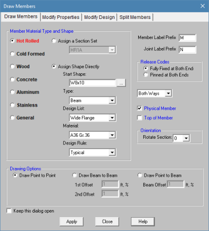
The Member Drawing Options are as follows:
Use the first mouse click to select the start point of the new member. Use the second mouse click to select the end point of the new member.
Use the first mouse click to select the start point of the new member. Use the second mouse click to select an existing member which would contain the end point of the new member. ‘Beam Offset’ is the offset of the end point of the new member from the start point of the existing member.
Use the first mouse click to select an existing member which would contain the start node of the new member. Use the second mouse click to select an existing member which would contain the end point of the new member. ‘1st Offset’ and ‘2nd Offset’ are the location offsets of the start and end points of the new member from the start points of the existing members.
 on the RISA Toolbar to open a new
view and click
on the RISA Toolbar to open a new
view and click  to turn on the Drawing
Toolbar if it is not already displayed.
to turn on the Drawing
Toolbar if it is not already displayed. button and set the
 The first click will define the I-end of the first
The new
Note
 button.
There are a number of ways to modify
The graphical Modify Members tool discussed here lets you modify the
properties of
on the RISA Toolbar to open a new
view and click to turn on the Drawing
Toolbar if it is not already displayed. and then click the item.
To modify a few
To modify a selection of
Note
button.The parameters shown are nearly the same as those used to define new
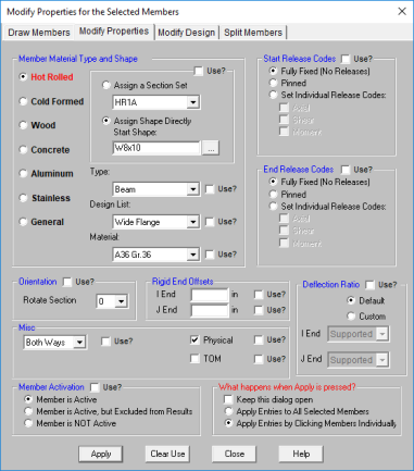
The Use? check boxes next to the data fields indicate whether
the particular parameter will be used or not when the modification is
applied. If the box next to a field is checked, that parameter will
be applied to any selected
Member material and cross section properties may be assigned to a member in one of two ways – either directly by specifying the shape and material explicitly, or by assigning a Section Set to the member. Section Sets allow you to control properties for a group of members that share the same properties. Combining section sets with the Member Redesign feature gives you great control over how new member sizes are picked and what members get updated. Section sets must be used when the desired shape is not in the database or when steel redesign (optimization) is desired. See Section Sets for more information.
All member properties may be assigned graphically either as you draw or later as a modification to the members.
You can graphically specify the Hot Rolled, Cold Formed, Wood, Aluminum, or Concrete design parameters such as unbraced lengths and K factors. See Steel Design, Cold Formed Steel Design, Concrete Design, Aluminum Design, and Wood Design for information on the design parameters themselves.
To use this, you will specify the appropriate member parameters, then select the members that you want to modify, and then click on the "Apply" button. Alternately you can set the parameters and then choose the "Click to Apply" option, which allows you to then click on the members you want modified.
To Modify Member Design Parameters
on the RISA Toolbar to open a new
view and click to turn on the Drawing
Toolbar if it is not already displayed. button
and select the Modify Design tab.To modify a few members choose Apply Entry by Clicking Items Individually and click Apply. Click on the members with the left mouse button.
To modify a selection, choose Apply Entries to All Selected Items and click Apply.
Note
button.The parameters shown are the same as those on the Hot Rolled, Cold Formed, Wood, Aluminum, or Concrete tab of the Members spreadsheet.
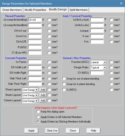
The Use? check boxes next to the data fields indicate whether the particular parameter will be used or not when the modification is applied. If the box next to a field is checked, that parameter will be applied to any selected members, if the box is NOT checked, the parameter will NOT be applied, even if a value is entered in the field. This lets you easily change one or two properties on members without affecting all the rest of the properties. Note that if no value is entered in a field (I.e. the field is blank) and the corresponding check box is checked, clicking "Apply" will have the effect of clearing the data for these fields. For example, to remove all member end-releases for the currently selected members, just erase any text in the I and J release fields, click their Use? check boxes so that they're checked, and then click on "Apply".
You can split members into a number of equal length pieces or you may split into two members at a specified location from the I joint. You may specify the split location as a length or a percentage of length. For example specifying %50 will split the members at the midpoints.
You may choose between Add Joints to Physical Members and Actually Split Physical Members. For Physical members it is likely that you will not want to actually split the member but prefer instead that joints be placed along the member so that you may specify other members, plates, loads or boundary conditions.
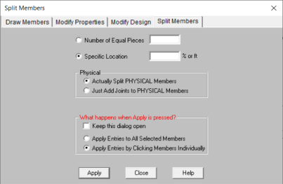
If you use both parameters at the same time, each parameter will be applied independently to the original member. For example if you specify '3' equal pieces and also specify a split at '%50', you will get a member that is broken up in 3 places. There will be 2 breaks at its third points, and also a break that would be at the middle (50% of the length) of the original member.
on the RISA Toolbar to open a new
view and click to turn on the Drawing
Toolbar if it is not already displayed. button
and select the Split Members tab. To modify a few members choose Apply Entry by Clicking Items Individually and click Apply. Click on the members with the left mouse button.
To modify a selection, choose Apply Entries to All Selected Items and click Apply.
Note
button.The Members Spreadsheet records the properties for the
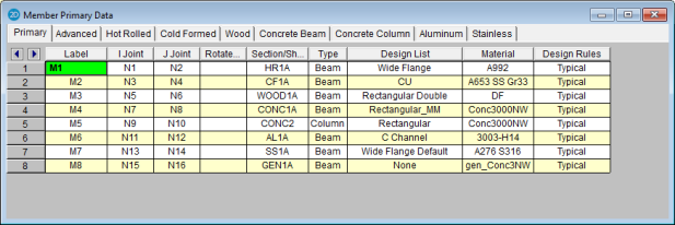
The following data columns hold the
You may assign a unique Label to any or all of the
The I-Joint and J-Joint entries define the start (I-joint) and end (J-joint) locations of the member. The member local axes are defined based on these joints. See Member Local Axes for more information.
The Rotate column is used to define the orientation of the member cross-section. You may specify 0, 90, 180 or 270 degree rotations. See Member Local Axes and Defining Member Orientation for more information.
If you are explicitly assigning shapes to each member, then enter the database shape you wish to use for the member. You can select this by clicking on the arrow in the cell. Alternatively, you may choose a section set to represent the section properties, material properties, and re-design parameters.
If you are explicitly assigning shapes to each member, then you may enter the member type that you wish to use. The choices are Column, Beam, Vertical Brace, and Horizontal Brace.
Here are the main effects that the member type will have on your structure:
1) If you are using concrete, this will define the rebar layout (column vs beam) .
2) If you are using design lists, they specifically reference the member type.
3) If you are using member area loads, loads will not be attributed to members defined as Hbraces or Vbraces.
4) If you are using flexible diaphragms, transient loads will not be attributed to members defined as None, Columns or Vbraces.
5) If you are using the RISA-Revit link the link will not work properly unless you use member types.
6) If you are integrating with RISAConnection, the connection validation requires proper use of member types.
7) If you are using the seismic detailing provisions then you must use proper member types.
Note
If you are explicitly assigning shapes to each member, then you may enter the design list type that you wish to use. This entry will affect the members that are available to program when it is suggesting alternate or optimized shapes. Refer to Design Optimization for more information on the member optimization procedure. Also refer to Appendix A – Redesign Lists for information on creating or editing these lists.
Note
If you are explicitly assigning shapes to each member, then you may enter the material that you wish to use. You can select this by clicking on the arrow in the cell.
Note
If you are explicitly assigning shapes to each member, then you may enter the design rules type that you wish to use. When the program is checking alternate or optimized shapes, it will restrict its selections to members that obey the chosen design rules. Refer to Design Rules– Size / U.C. for more information.
Note
The Advanced tab records the properties for the member elements and may be accessed by selecting Members on the Spreadsheets Menu.
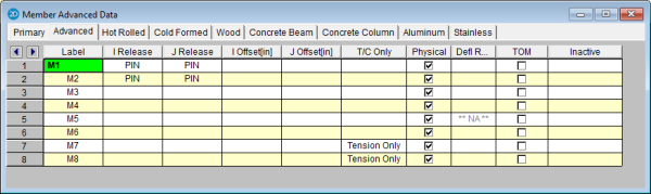
The following data columns hold the Advanced data for the members:
Releases control the forces that may be resisted by a member. You may use these to define pinned connections, truss members, and any other end condition. See Member End Releases for more information.
End offsets may be used to model a rigid end zone for a member. See Member End Offsets for more information.
The T/C field is used to indicate that a member is to be Tension or Compression only. When a member is flagged as C, any members it will only be able to take compressive loads. The member will have no stiffness to resist tensile loads. When a member is flagged as T, the member will only be able to take tension loads. When a section is flagged as E, the member will primarily take only tension loads, however it will also take some compression load, up to its Euler buckling load.
This box is checked if the member is a Physical Member. See Physical Members for more information.
This option is only applicable to members designated as beams. This field is used to designate the member end behavior either as supported or as a cantilever for the deflection ratio. If this field is blank, deflection ratio will be based on original member behavior. See Deflection Ratio Options to learn more.
Members may be offset downward by half their depth for analysis. This is useful for aligning all of your beams to the same top of steel elevation. See Top of Member Offset to learn more.
Members may be removed from the solution without deleting them from your model by making them inactive. See Inactive and Excluded Elements for more information.
Members in RISA by default are allowed to take both tension and compression. However, some design or modeling practices may require you to define specific members as either Compression Only or Tension Only. Here we will define what each of the T/C Only options means.
This is the default behavior. In this scenario a member will be allowed to take either compression or tension and the program will base the combined bending and axial code checks on these forces.
Tension-only behavior is just as it sounds. When a member is defined as tension-only the program will allow these members to only resist tension forces. If the load path introduces compression forces into the member, then it will be removed from the stiffness matrix and another solution will be run.
Note
An option similar to tension-only is the Euler buckling option. This option is used as a replacement to tension-only and allows a member to take up to the Euler buckling capacity of the member in compression before it is removed.
The reason for the Euler buckling option is that allowing tension-only members to take a little compression helps model convergence greatly. Generally speaking, tension-only members are generally very slender members that have a small Euler buckling capacity. The intent of this option is to allow a very small amount of compression to get into your members so you don't get unstable models.
Note
Compression-only behavior is just as it sounds. When a member is defined as compression-only the program will allow these members to only resist compression forces. If there are tension forces then the member will be removed and another solution will be run.
Note
When a model contains T/C only members, the program must iterate the solution until it converges. Each iteration is a solution of the model. After each solution the program checks T/C only member forces. If a tension-only member has compression then this member has it's stiffness reduced down to 1e-8% of it's original stiffness so it will take no forces. If an Euler buckling member has a compression greater than its Euler buckling load this member has it's stiffness reduced down to 1e-8% of it's original stiffness. If a compression-only member has tension then this member has it's stiffness reduced in a similar fashion. After these member stiffnesses are reduced the stiffness matrix is re-built and another solution is run.
In subsequent solutions members can have their stiffnesses both removed and added back in. Reducing the stiffness of members is the identical process just explained. Adding member stiffness back in can occur for members that have been previously reduced. The program will look at the distance between the end nodes which define the previously reduced member. From this distance the program can calculate whether that member would now be in compression or tension. Let's take a tension-only member that had it's stiffness reduced due to the presence of compression in the first iteration. In the 2nd iteration if the distance between the nodes defining the member got longer than it was in iteration one, this would signify that the member would now be in tension. Thus, for the next iteration the program would place this member back in the stiffness matrix.
Because of this iterative solution, models with T/C only members can take a bit longer to solve than a regular static solution.
Note
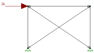
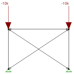
For members defined as tension-only you can run into problems with instabilities for gravity-only LC's. For example, let's take a look at an x-braced frame where the x-bracing is defined as tension-only. For a lateral load combination, the tension-only feature works great.
|
|
In the image above we can see that the "compression" brace has no force in it because it has it's stiffness reduced in the stiffness matrix and that all of the load is passing through the "tension" brace.
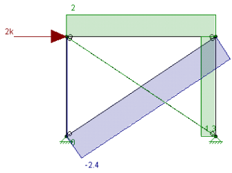
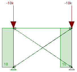
However, if we are looking at a gravity load combination, this results in an instability.
|
|
In this scenario the columns in this model undergo a small amount of axial shortening. This induces a small amount of compression and both of the tension-only braces have their stiffnesses reduced. This results in a frame that is unstable and illustrates the problem. The solution here is to use Euler buckling braces.
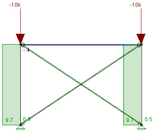
In this case these braces are taking about 500 lbs of compression, a relatively small amount. As long as this value is small then we can still consider these as tension-only members.
Note
Just as with the joints and plates you may double-click any member to view it’s properties. All of the same information that is stored in the Members and Member Design spreadsheets is displayed for the member you choose, and may be edited. This is a quick way to view and change member properties. For large selections of members however the spreadsheet and graphic editing tools may be the faster solution.
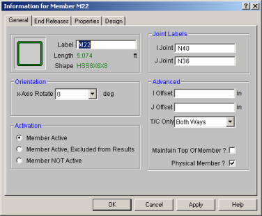
General - This tab let’s you view edit the member’s label and end joints. The rigid end offsets, orientation, and activation state can also be viewed and modified here. The shape pictured will change depending on the shape type of the member. It will also change to reflect wood members. If the member is made inactive here, you will need to activate the member from the Members spreadsheet, or by using the Criteria Select feature to find and select inactive members.
End Releases - This tab allows you to view and modify the end releases for the member. It also allows you to define Connection Rules for your hot-rolled steel connection design to be used in conjunction with RISAConnection. See the RISAConnection Integration topic for more information.
Properties - This tab lets you view and edit the member’s section set. The type of material information displayed will change depending on whether the section set material properties are defined on the General Materials spreadsheet.
Design - This tab allows you to view and edit the design properties for the member. The types of design information will change depending on the material type of the member and the code setting on the Model Settings window.
Detailing - This tab is specifically for you with the CIS\2 translator export application. THIS TAB DOES NOT AFFECT ANALYSIS
Note
Physical Members provide fixity to all joints that occur along the length of the member, without breaking that member into multiple smaller members. You may use the physical member feature to avoid defining one 'field' member with multiple members in your model. This saves time in building and editing your model and in understanding your results.
To define a Physical Member, check the Physical Member box in the Set Member Properties settings or in the Modify Member Parameters settings. You may also specify Physical Members in the Members Spreadsheet and in the Member Information settings.
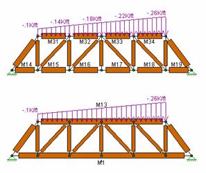
To understand the benefits of Physical Members see the trusses in the following figure. The first truss shows the chords modeled without physical members and thus with multiple members modeling each chord. The second truss models each chord with one Physical Member. Both models will yield the same results. However the Physical Member model is more intuitive and easier to work with because you don’t have to work with multiple members when you create the chords, load them, edit them or evaluate their results. Notice that the distributed load may be defined from start to end for the Physical Member. In the other model the distributed load end magnitudes have to be specified for each of five members in order for the entire load to be defined.
Continuous beams
Physical Members are also effective in managing results because the
results for one Physical Member are reported together in the results spreadsheets
and the
Note
For additional advice on this topic, please see the RISA Tips & Tricks webpage at risa.com/post/support. Type in Search keywords: What are Physical Members.
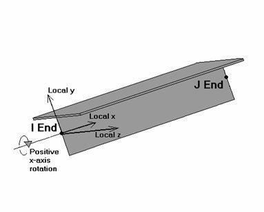
The following diagram illustrates the directions of the member's local axes that are used to define member forces, stresses, and deflections as well as loads defined in local axes directions:
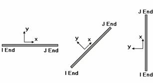
As can be seen from the diagram, the local x-axis corresponds to the member centerline. The centerline designates the member cross section's centroid location. The positive direction of this local x-axis is from the I-joint towards the J joint. The local z-axis is always normal to the plane of the model with positive z being towards you. The local y-axis is then defined by the right-hand rule.
![]()
In RISA-2D if you do not explicitly define the orientation for the member, the usual default is for the member to bend about it’s “strong axis”. The third column on the Members spreadsheet, Rotate, is used to define the orientation of the member cross-section. You may specify 0, 90, 180 or 270 degree rotations.
As an example, to have a wide flange (WF) member bend about it’s strong axis this field should be left blank or set to “0”. To have a WF bend about it’s weak axis, enter a “90” in this field.
For another example consider a Tee shape as shown below. Remember that when modeling the local z-axis is always towards you.
Note
 button on the Window toolbar.
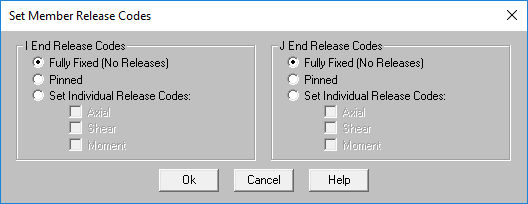
The I Release and J Release fields are used to designate whether the forces and moments at the ends of the member are considered fixed to or released from the member's points of attachment (the I and J joints). Each member has 3 force components at each end (axial, shear, and bending). Any or all of these force components can be released from the member's point of attachment. If a force component is released, that force is not transferred between the joint and the member.
To specify member releases go to the I Release or J Release
field for the member in the Members Spreadsheet on the Advanced Tab, click the  button,
and specify the condition.
button,
and specify the condition.
Alternatively, you may specify the end condition by directly typing in the field. To indicate that a force component is released, put a X for that component in the release field. You can move within the release field using the space bar which will result in a O for no release.
RISA-2D has a special "keyword" release configurations built-in. This is:
PIN => M(bending only) released (OOX)
This keyword entry is included because 99% of the release configurations you'll ever want to define will be one of these two (98% will be BenPIN). You can call out the keyword entry by just entering the first letter of the keyword. So if you go to a release field and enter "bp", the keyword "BenPIN" will be filled in automatically.
For additional advice on this topic, please see the RISA Tips & Tricks webpage at risa.com/post/support. Type in Search keywords: End Release.
The Beam Deflection Ratio can be used during member design to check the deflection criteria. By default, the program will determine whether a member is a cantilever or is supported on both ends. In certain cases where the beam should be considered otherwise, more control over these support types for a beam can be designated in the Deflection Ratio Options. This feature is only applicable to members designated as "beams" and only affects the beam deflection ratios located in the Beam Deflection tab of the Member Deflections spreadsheet.
The option to set the support type for the beam deflection ratio can be applied from any of the following locations:
Clicking the  button in the spreadsheet brings up the following dialog box:
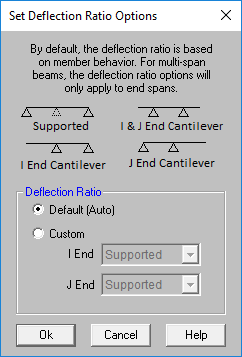
Single span beams can be designated as supported on both ends, or cantilever on either I- or J- end. Multi-span beams have an additional option to be cantilever on both I- and J- end. A double cantilever option is available for multi-span beams since internal supports will support the beam. Designating member ends as either supported or cantilever will affect only the beam relative deflection and also determine which equation is used when calculating beam deflection ratios. See Beam Deflections.
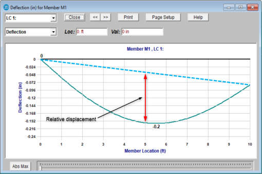
For a member supported on both ends, the maximum relative displacement used in the beam deflection ratio will be the largest straight line distance (in the vertical y direction) between the deflected shape and the original undeflected shape.
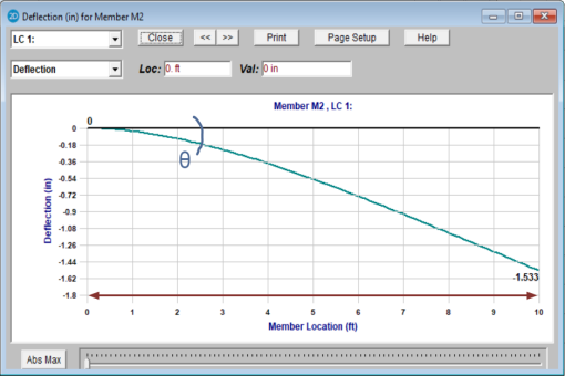
For members with a cantilever end, the location of the maximum relative deflection will be at the free end of the member. The displacement value is equal to the rotation at the supported end multiplied by the length of the member.
Note
The Member Top Offset is an offset applied downward to the member which acts to make the top of the member line up with the end joint elevation (i.e. the end joint elevation becomes the “top of the member”). When the TOM flag is checked on the Advanced tab of the Members spreadsheet, RISA-2D first calculates the distance from the member centroid to its extreme top fiber (in the current configuration) then offsets the member that distance in the negative Global vertical direction.
This feature reflects the fact that members may be aligned by their faces rather than by their centerline elevations such as when you have a W24 and a W12 framing into the same column. Members with this flag set will be offset downward (in the negative vertical direction) from their joint endpoints. The distance of the offset will be the distance from the centroid to the top of the beam. For example, a beam in strong axis bending will be offset half its depth. A beam turned 90 degrees so that it is in weak-axis bending will be offset by half its width. For singly-symmetric sections such as single and double angles and WTs, RISA-2D will correctly identify the member orientation and vertical offset distance necessary to properly align the member’s “top” edge. This offset affects the member stiffness and results. All member results for offset members will be reported at the ends of the member, not at the joint locations.
Note
Member offsets reflect the fact that the member ends may not be attached at the centerline of the member being attached to. For example, a beam connected to the flange of a column is offset from the centerline of the column. The distance of the offset would be ½ the depth of the column.
You may enter explicit offset distances or have them calculated automatically. To enter offsets explicitly simply enter the value of the offset. To have the offset calculated, enter the non-numeric label of the member whose depth defines the offset distance.
For example, say your member is framing into the flange of a 12" deep column. The offset distance would be 6", so you would enter '6' for the offset. Now, if that column gets changed to a 14" shape, you would have to go back and change the offset distance to 7". This can be time consuming if you have many offsets.
If instead the column has a label of M100, specifying M100 as the member offset causes the offset to be calculated as half of the depth of the member M100. For the W12 column the offset would be 6" and when the column is changed to a W14 the offset becomes 7".
Note
For additional advice on this topic, please see the RISA Tips & Tricks webpage at risa.com/post/support. Type in Search keywords: Offsets.
Making an element, such as a member, plate or wall panel, inactive allows you to analyze the structure without the item, without having to delete the information that defines it. This leaves data intact so the item may be easily reactivated. This is handy if you want to try a frame with and then without certain items, without having to actually delete the data.
Making an element Inactive means the item is not included when the model is solved or plotted.
Making an element Excluded means the item is in the solution, but excluded from the results list. An excluded item will be treated like any other member in the solution and plotting of the model, but the item will not be listed in the solution results (forces, stresses, deflections, etc.). This is useful if there are certain items whose results you're not interested in. You don't have to clutter up the results with these items and can concentrate on the items you're most interested in. See Printing for more limiting printed results.
Note
Including shear deformation models the effects of shearing forces on the lateral displacements of the members. Shear deformation is included in the analysis by checking the appropriate box on the Model Settings.
Shear deformation effects are based on the material shear modulus (G) and the shear area.
Including shear deformation causes the member stiffness matrix to be modified by the term M, where:
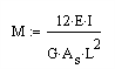
Where As = Area * Shear Deformation Factor
These shear area coefficients will be automatically calculated for all standard members, but must be entered for arbitrary sections. While these shear deformation factors are always less than 1.0, they can vary from 0.85 for solid rectangular shapes, to 0.88 for solid circular shapes, to 0.53 for thin pipes. These coefficients are used strictly for shear deformation effects and should not to be confused with shear stress factors described in the next section. A good reference for the calculation of both of these coefficients is Stress, Strain, and Structural Matrices by Walter D. Pilkey.
For members whose length is much greater than the depth, shear deformation has a relatively minor impact. When the length of the member is less than 10 times its depth, shear deformation begins to have a significant impact on the solution. Keep this in mind if you are creating models where members are being broken up into several pieces because the length used to calculate the term M is the joint-to-joint member length.
Note
The equation for calculating shear area varies for different shape types:
Since shear stress is not equally distributed over a cross section,
it is unconservative to take the maximum shear stress as simply the beam
shear (V) divided by the beam’s cross sectional area. To achieve
more accurate results you must reduce the shear area by a shear stress
factor, 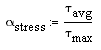
where:

and

These shear stress factors will be automatically calculated for all standard members, but must be entered for arbitrary sections. While these shear area coefficients are always less than 1.0, they can vary significantly. Common values include 0.67 for solid rectangular shapes, and 0.75 for solid circular shapes.
Note