3. Assign Connection Rules
Once the Connection Rules are defined they must be applied to the member ends in your model.
- For Column/Beam connections the rule is assigned to the beam end but not the column.
- For Girder/Beam connections the rule is assigned to the beam end but not the girder.
- For Column/Beam/Brace connections the rule is assigned to the beam and brace(s) ends but not the column.
- For Chevron Brace connections the rule is assigned to the brace ends but not the beam.
- For Knee Brace connections the rule is assigned to the brace ends but not the supporting beam or column.
- For Splice connections, the rule is assigned to both of the Column or Beam ends.
Assigning Connection Rules in the Properties Panel
To Assign Connection Rules:
-
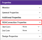
Click on a member and expand the RISAConnection Properties section in the ‘Properties’ panel, as shown in the following image.
Click on image to enlarge it
-
For both the Start and End of the member, click the down-arrow and choose the proper Connection Rule.
You can apply a Connection Rule to one member at a time, or select multiple members to assign a Connection Rule to multiple members.
Assigning Connection Rules in the Members Spreadsheet
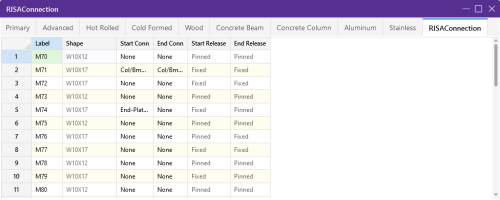
The
Click on image to enlarge it
RISAConnection Spreadsheet Columns
|
Column |
Description |
|---|---|
|
Label |
Displays the name of the member for all Hot rolled Steel members in the |
|
Shape |
Allows you to view what shape is assigned to the member. |
|
Start/End Conn |
Allows you to select a rule from the ‘Connection Rules’ spreadsheet. You need to know which end of the member is the Start (I end) and the End (J end), which you can view graphically. |
|
Start Release/End Release |
Displays the end release for the beam. This is useful in verifying that the chosen connection for the beam is valid for its end fixity (i.e. sheer connection for pinned-end beams). |
Viewing Connection Rules Graphically
The ‘Quick View’ toolbar can be used to view the assigned connection rules directly on your model.
To view the assigned Connection rules using the Quick View toolbar:
-
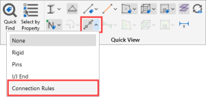
Click the Member Ends icon’s down-arrow on the Quick View toolbar.
Click on image to enlarge it
-
Choose Connection Rules from the list that appears.
-
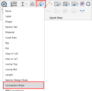
Click the Member Label icon’s down-arrow on the Quick View toolbar.
Click on image to enlarge it
-
Choose Connection Rules from the list that appears.
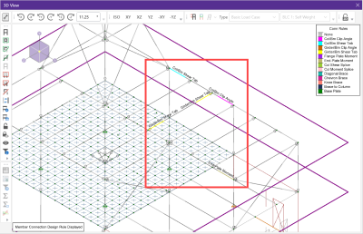
The following image shows how the members with connection rules applied appear in color-coded view, along with their labels.
Click on image to enlarge it
