Project Grid
The Project Grid provides convenient snap points for modeling columns and walls in buildings and building-type structures. It also provides convenient terminology to refer to locations in a model, such as "Grid Intersection C-4". The Project Grid is intended to be a permanent part of the model so unlike the Drawing Grid it is saved with the model.
Show / Hide Project Grid Lines
To view (or hide) Project Grid lines:
-
Go to the View ribbon.

Click on image to enlarge it
-
Click the Project Grid icon to toggle the display of the Project Grid lines “on”.
The project grid lines appear in the model viewing panel.

Click on image to enlarge it
-
(Optional) Click the Project Grid icon again to toggle the display of the lines “off”.

Show / Hide Project Grid Arcs
To view (or hide) the Project Grid arcs:
-
Go to the View ribbon.
-
Click the Project Grid icon to toggle the display of the arcs “on”.
The project grid arcs appear in the model viewing panel.

Click on image to enlarge it
-
(Optional) Click the Project Grid icon again to toggle the display of the arcs “off”.

Project Grid Spreadsheet
To open the Project Grid spreadsheet:
-
Click on Project Grid under ‘Data Entry’ in the ‘Explorer’ panel.
The Project Grid window opens to the Lines tab.
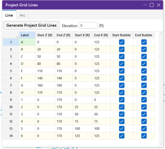
Each Grid Line (as opposed to Grid Arcs) is defined by Start and End coordinates along the X and Z axes. This method of defining grids allows them to be oriented in any direction, including skewed grids or non-parallel grids within the same building.
-
(Optional) Click the Arcs tab to view the generated arcs.
Project Grid Line Generation
Project Grid lines can be generated from the Project Grid spreadsheet or from the Home ribbon.
To generate project grid lines:
-
Do one of the following.
Project Grid spreadsheet - if you have the spreadsheet open:

Click on image to enlarge it
-
Click on the Line tab if not already displayed.
-
Click the Generate Project Grid Lines button.
Home ribbon:
-
Click the Project Grid icon.

Click on image to enlarge it
-
Click on Straight Grid Generator.
The Project Grid Lines generation window opens to the Lines tab.

Click on image to enlarge it
The generator provides the ability to generate an entire grid system at once rather than entering the grids in manually in the project grid spreadsheet.
-
You can use symbols such as "@", "/" and "," when entering the increments.
-
The "@" entry can be used to specify multiple, equally spaced, grid increments.
For example, if you wanted 7 increments at 10 units each, you would type "7@10" in the increment field.
-
The "/" entry subdivides a larger increment into smaller equal increments.
For example, the entry "12/4" would create 4 increments of 3 units each.
-
Use commas (",") to enter multiple increments in the increment field.
For example, if you wanted to define increments of 3, 4, 7 and 2 units, you could enter "3,4,7,2" in the increment field.
-
The Preview button lets you see the project gird lines prior to applying them.
-
The Preview and Undo buttons provide an easy way to preview a Project Grid before adding one to the model.
-
-
(Optional) Change the options to those you want applied.
Don’t forget to “Preview” your settings before you apply them.
-
Click Apply to generate and apply the project grid lines to the model.
Once the project grid is specified and displayed in the model view, it provides snap points while drawing your model.


Project Grid Arc Generation
Project Grid arcs can be generated from the Project Grid spreadsheet or from the Home ribbon.
To generate project grid arcs:
-
Do one of the following.
Project Grid spreadsheet - if you have the spreadsheet open:

Click on image to enlarge it
-
Click on the Arc tab if not already displayed.
-
Click the Generate Project Grid Arcs button.
Home ribbon:
-
Click the Project Grid icon.

Click on image to enlarge it
-
Click on Arc Grid Generator.
The Project Grid Arcs generation window opens to the Arcs tab.

Click on image to enlarge it
The generator provides the ability to generate an entire grid system at once rather than entering the grids in manually in the project grid spreadsheet.
-
You can use symbols such as "@", "/" and "," when entering the increments.
-
The "@" entry can be used to specify multiple, equally spaced, grid increments.
For example, if you wanted 7 increments at 10 units each, you would type "7@10" in the increment field.
-
The "/" entry subdivides a larger increment into smaller equal increments.
For example, the entry "12/4" would create 4 increments of 3 units each.
-
Use commas (",") to enter multiple increments in the increment field.
For example, if you wanted to define increments of 3, 4, 7 and 2 units, you could enter "3,4,7,2" in the increment field.
-
The Preview button lets you see the project gird arcs prior to applying them.
-
The Preview and Undo buttons provide an easy way to preview a Project Grid before adding one to the model.
-
-
(Optional) Change the options to those you want applied.
Don’t forget to “Preview” your settings before you apply them.
-
Click Apply to generate and apply the project grid arcs to the model.
Once the project grid is specified and displayed in the model view, it provides snap points while drawing your model.


Edit the Project Grid Lines (Adding or Moving Grid Lines)
Once a Project Grid has been created the grid lines can be moved, or additional grid lines can be created, by double clicking on a grid line in the model view.

Click on image to enlarge it
The Generate Parallel Line button allows a line to be created by offsetting an existing grid line.

Click on image to enlarge it
The Move Lines button allows a grid line to be moved by a specified distance. A positive distance moves the line in the positive global direction, while a negative distance moves the line in the opposite direction.

Click on image to enlarge it
Edit the Project Grid Arcs (Adding or Moving Grid Arcs)
Once the Project Grid Arcs have been created, an arc’s shape can be changed by double clicking on it in the model view and modifying its settings.

Click on image to enlarge it