Diaphragms provide lateral load distribution functions, and are necessary for automatic Wind and Seismic load generation. There are three fundamental types of diaphragms in structural modeling:
Note:
For additional advice on this topic, please see the RISA Tips & Tricks webpage at risa.com/post/support. Type in Search keywords: Diaphragms.
|
|
|
| RISAFloor linked with RISA-3D Includes Rigid and Flexible Diaphragms |
Rigid diaphragms represent a plane of very high rigidity. Rigid diaphragms distribute load to elements which connect to them solely based on the stiffness of the elements. They achieve this by tying all of the
Note:
Loads applied within the plane of a diaphragm will be attributed to all elements which connect to the diaphragm. The amount of load which each element takes is proportional to its stiffness. Diaphragms are capable of both translation and rotation, so the torsional effects of the moment arm between the center of load and the center of rigidity are accounted for. This is also true for a dynamic mass which is offset from the center of rigidity.
Because a rigid diaphragm is part of the stiffness matrix, an explicit Center of Rigidity is not calculated or reported. Internally, the program creates a hidden set of rigid links which interconnect all of the

All
Rigid Diaphragms must be defined along the Global Axes, therefore they can only exist in the XY, XZ, or YZ planes. If rigid behavior is desired along a plane other than these, a semi-rigid diaphragm (made of plates) with a large stiffness value can be used instead.
The stiffness of the rigid diaphragm is set to a unitless value of 1 x 10⁷ by default. This value has been calibrated as providing the best behavior for most models. It can be adjusted from within the diaphragms spreadsheet, however adjusting this value is only recommended in the following circumstances:
To adjust the diaphragm stiffness, right-click on the diaphragms spreadsheet and select Set Diaphragm Stiffness button
A RISA-3D model that is linked up to RISAFloor has an automatic rigid diaphragm analysis and design. Each individual slab/deck polygon is converted to a rigid diaphragm within RISA-3D. Therefore, it is possible to have multiple independent diaphragms at any given floor elevation.
A semi-rigid diaphragm is one which distributes loads based on both the stiffness of elements which connect to it and on the stiffness of the diaphragm itself.
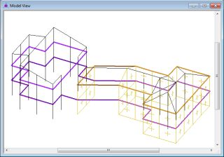
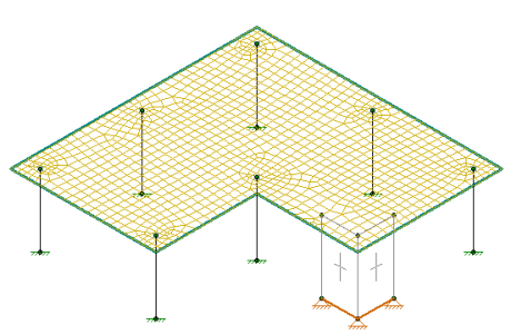
The Semi-Rigid diaphragm in RISA-3D will help you distribute the lateral forces based on the stiffness of the slab. When RISA-3D is integrated with RISAFloor the program can create a Semi-Rigid diaphragm automatically. The Semi-Rigid diaphragm is defined in Diaphragm Parameters in a Beam Supported Floor and the Slab Definitions spreadsheet in a Concrete Floor Slab. During the integration between RISAFloor and RISA-3D, the program creates a mesh of FEA plate elements within the edges of the slab. The thickness of the plates is defined by the slab/diaphragm defined in RISAFloor. The plate elements are automatically submeshed so that they attach to all vertical elements (columns and walls) as well as any new members or loads added into the RISA-3D model. Below shows an example of a simple L-shaped building with the mesh displayed..
When the model is in RISA-3D, the mesh size is controlled by the Model Settings - Solution Tab -Semi-Rigid Mesh . For RISAFloor ES models, the slab stiffness can be reduced based on the Icr factor in the RISAFloor Slabs spreadsheet and the Use Cracked Slabs checkbox in the Model Settings in RISA-3D. The Icr slab stiffness only affects the out-of-plane stiffness. For further information on cracked slabs, see Elevated Slabs - Analysis. The top of the columns are fixed to the diaphragm using links to distribute the forces over a 12"x12" area rather than a single column node. For further information see the Column Meshing section of the help.
Note:
Lateral Elements: When modeling with a Semi-Rigid diaphragm, it's important to make all columns and walls Lateral. This will bring all the columns and walls into RISA-3D which will support the slab as the vertical loads are applied. In RISA-3D, the program will apply both lateral and vertical loads to the diaphragm for analysis of the lateral system. This is different than Rigid diaphragms because only the lateral resisting system needs to be transferred into RISA-3D.
Reinforcement Design: RISA-3D will not design the reinforcement for the slab. The reinforcement is designed in RISAFloor and is based on the vertical loads. However, you can find forces in the slab in RISA-3D using the tools listed below.
Vertical Loads: The semi-rigid diaphragm has self weight and out-of-plane stiffness. Internally, the plates are modeled as normal so that there is stiffness out-of-plane. The diaphragm is used for out-of-plane and in-plane load distribution.
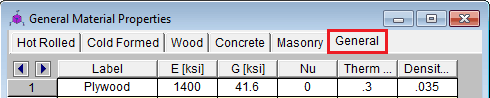
Diaphragm Material:The Semi-Rigid diaphragm material uses the General Materials. There are a list of default General Materials, however you can add to this list to match your diaphragm. See Materials for further information on creating your own General Material.
Diaphragm Thickness:The Semi-Rigid diaphragm thickness should be selected based on the approximate stiffness you expect from the slab or deck for lateral loading. The semi-rigid diaphragm is modeled using isotropic plates. Therefore, there is no association with the deck direction for the semi-rigid diaphragms. If your diaphragm is truely one-way, you may consider using a Flexible diaphragm.
RISA-3D does not have the ability to automatically define a Semi-Rigid diaphragm. However, Semi-Rigid diaphragms can be represented in the model using plates.
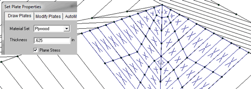
A semi-rigid diaphragm is modeled with plates, and requires you to model and submesh the plates appropriately. In order to adequately mesh your plates it is good to be familiar with Plate-Member Interaction. Plates are modeled using general materials, so the first step is to set up a material with the material properties of your diaphragm.
Next, model your plates using the specified material, and with an accurate thickness. Be sure to check the “Plane Stress” option. This makes it so that the plates only have stiffness within their own plane, and as a result won’t add any composite bending strength to the beams in the plane of the diaphragm.
Note:
Flexible diaphragms distribute loads to elements which connect to them solely based on the tributary area of the element within the plane of the diaphragm.
A flexible diaphragm can be defined in a combined RISAFloor/RISA-3D model. For wood diaphragms, the program will actually design the sheathing and nail spacing, incorporating the code specified design tables from the NDS/IBC. See the Diaphragms - Analysis & Results topic for more information on how the design works and how loads are attributed both for wind and seismic loads. The diaphragm can be defined as flexible when drawing the deck edge or from the Diaphragms spreadsheet.
|
|
Note:
Flexible diaphragms within RISAFloor/RISA-3D are used solely as load-attribution devices, and do not exist as elements within the stiffness matrix, unlike rigid or semi-rigid diaphragms. Flexible diaphragms have no stiffness, and are incapable of transferring load from one element within them to another. Thus, members that do not have lateral resistance out of plane are susceptible to stability issues. To increase stability in a model with a flexible diaphragm it may be necessary to add small springs in the out-of-plane directions on the frames at the tops of the columns. This will stabilize the members while generally having a minimal effect on the analysis of the model.
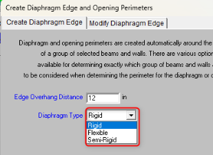
When a flexible diaphragm is applied to a sloped roof in RISAFloor, a setting exists to specify whether a ceiling diaphragm is present.
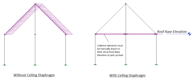
The load attribution for the flexible diaphragm will occur only for Lateral Members from RISAFloor when a ceiling diaphragm is not specified. This is illustrated above where the lateral load follows the rafters. When a ceiling diaphragm is specified, it is necessary to draw in collector beams at the ceiling elevation so that the load can be carried directly the columns or walls at the base of the sloped members. With a ceiling diaphragm, the sloped members will not experience any lateral load directly. Note that the same total amount of lateral force will be applied regardless of this setting. This only controls whether the lateral load is applied to the sloped members, or in a horizontal flat plane.
The Diaphragms Spreadsheet contains diaphragm information and may be accessed by selecting Diaphragms on the Spreadsheets menu under Data Entry. Alternatively, it can be accessed by clicking the button on the Data Entry Toolbar.
The diaphragms spreadsheet within RISAFloor is a simplified version of the diaphragms spreadsheet that is available from within the RISA-3D interface, which can be accessed via the Director Tool.
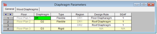
Floor displays the name of the Floor on which each diaphragm is located.
Diaphragm displays the diaphragm label. This label is used for the naming of Diaphragm Regions.
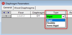
Type specifies whether the diaphragm is Rigid (Membrane) or Flexible for a Beam Supported Floor or Rigid (Membrane) or Semi-Rigid for Concrete Floor Slab. If a diaphragm has been defined as Flexible within RISAFloor it can be toggled between Rigid and Flexible in RISA-3D.
Region lists the diaphragm regions for each diaphragm. Diaphragm regions are used for the design of wood flexible diaphragms, and are also useful for explicitly defining how flexible load attribution is to be performed.
Design Rule specifies the Design Rule which is assigned to each region. Only the information on the Diaphragms tab of the Design Rules Spreadsheet is considered.
SGAF is the specific gravity adjustment factor for the design of wood flexible diaphragms. For more information see AF&PA NDS SDPWS, Table A4.2, Note 2. This value defaults to 1. However, it should be manually changed if the framing supporting the wood flexible diaphragm is not Douglas Fir-Larch or Southern Pine.
Note:
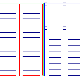
For buildings where a flexible diaphragm and rigid diaphragm occur on the same floor you can model the diaphragms using separate slab edges. This will require a gap between the framing of the two diaphragms however, such that load will not automatically be shared between the diaphragms.
Below is a screenshot of the gap for example:
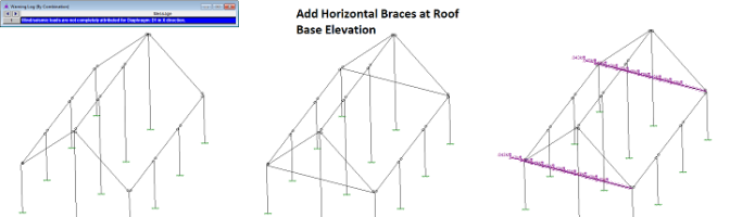
The flexible diaphragms at sloped roofs require members that are in the horizontal plane to attribute load to. These members must exist at the base roof elevation. For that reason, in the example below, the program reports "Loads are not attributed for Diaphragm". In the direction perpendicular to the ridge, there are no members for the program to attribute the wall wind loads to, so no loads are attributed to the diaphragm at all in that direction.
To correct this issue, simply draw horizontal bracing in the structure which can pick up the load and transmit it to the main lateral force resisting system.
For additional advice on this topic, please see the RISA Tips & Tricks webpage at risa.com/post/support. Type in Search keywords: Sloped Roofs.