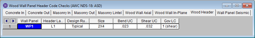
Wood Wall results are presented in the Wall Panel Design Spreadsheet and the detail reports.
For additional advice on this topic, please see the RISA Tips & Tricks webpage at risa.com/post/support. Type in Search keywords: Wood Walls.
See Wall Panels - Results for this topic.
The program will calculate the self weight of a wood wall based on the weights of the individual components. Using the material density, the self weight is calculated for the studs, chords, top plates, sill plates, and sheathing. These are all then summed for the total self weight of the wall.
The detail report gives detailed information about the wall design. The detail reports are specifically molded to the type of design specified. Here we will walk through how to access the different information for each of the types of design: Segmented, Perforated and Force Transfer Around Openings.
Note:
Once you have a solved model, the detail reports become available. They are accessible in two ways:
 . This will open up the detail report window.
 button that will open up the detail report window.
Note:
Once the detail report window is open, you will see a dialog area at the top.
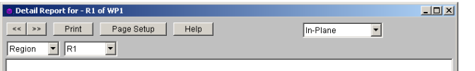
 - Allows you to click between the different wall panels in your model.
 - This button will allow you to take a snapshot of the current detail report you are viewing so that it can be added to a report. View the Printing topic for more information.
  - This dropdown list allows you to select between the three different parts of the wood wall panel detail report. Below we will explain the importance of each of these sections.
 - This dropdown list allows you to select between different regions or headers defined within the individual wall panel.
The Wall detail report gives an overall summary of your wall, complete with governing code checks and opening information. The Opening detail report gives information to the header design for the opening as well as detailed information for the Force Transfer Around Openings method. The Region detail report only applies for Segmented walls. Below we have give detailed information on each type of design: Segmented, Perforated and Force Transfer Around Openings.
The Segmented design method uses each of the three detail report windows to give design information.
This window gives an overview of the wall, giving controlling region information and deflection information. Note that this window only gives information on the full-height segments in your wall, as this is the basis of the Segmented method.
Input Echo
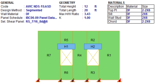
This lists information about the wall, similar to the Region report and also gives an image of the wall. The image shows the location of hold-downs/straps, regions and headers.
Design Details
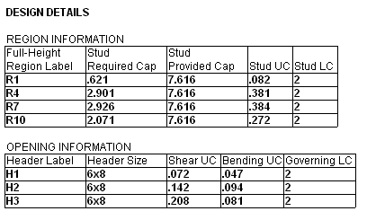
The Region Information gives the tabulated results of all of the full-height regions in your wall.
This window defines the openings in the wall. The segmented wall design method assumes zero stiffness over the opening, therefore, there is no header design for a Segmented wall with openings. Walls specified as a Perforated or FTAO can be analyzed for a header design.
This window gives information for your wall on a region by region basis. Note that only full-height regions of the wall panel will have a region detail report. The Segmented method only considers these full height segments in the design of the wall.
The region detail report is split into four portions: input echo, diagrams and design, design details, and cross section detailing. Note that in RISAFloor the detail reports are less detailed because RISAFloor does not consider lateral forces which RISA-3D does.
Input Echo
Below is the input echo portion of the detail report.
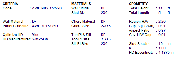
| Criteria | Description |
|---|---|
| Code | Gives the code used to design your wall panel. |
| Wall Material | Specifies the wood type assigned to the entire wall |
| Materials | Description |
|---|---|
| Wall Studs |
Specifies the wood material type assigned to the wall studs |
| Stud Size |
Specifies the member size used for the wall studs |
| Chord Material |
Specifies the wood material type assigned to the chords (vertical members at both ends of the wall) |
| Chord Size |
Specifies the member size used for the chords (vertical members at both ends of the wall) |
| Top Plate & Sill |
Specifies the wood material type assigned to the top and sill plates |
| Top Plate Size | Specifies the member size used for the top plate |
| Sill Plate Size | Specifies the member size used for the sill plate |
| Geometry | Description |
|---|---|
| Total Height |
This is the height of the wall panel region |
| Total Length |
This is the length of the wall panel region |
| Region H/W Ratio | This is the ratio of wall height to length, using the minimum wall height |
| Cap. Adj (2w/h) | This is an aspect ratio reduction factor for the shear panel strength per NDS SDPWS section 4.3.3.4 Exception 1 (2021/2015). This factor applies only for seismic loads, thus it will be 1.0 for wind load combinations per NDS SDPWS section 4.3.4.1 (2005/8). This factor is applied separately for each full-height region in your wall. |
| Aspect Ratio | This is an aspect ratio reduction factor for the shear panel strength per NDS SDPWS section 4.3.4.2 (2021/2015). This factor applies only for seismic and wind loads on Segmented or FTAO walls. This factor is applied separately for each region in your wall. |
| Gov. H/W Cap. | This is the governing (minimum) factor per the Cap. Adj (2w/h) and Aspect Ratios shown above. Only the minimum shall apply per NDS SDPWS section 4.3.3.4 Exception 1. |
| Stud Spacing | This is the optimized stud spacing based on your Design Rules |
| K | This is the effective length, K Factor used for stud and chord compression design |
| HD Eccentricity | This is the eccentricity of the hold-down connection. This is based on the manufacturer's catalog and measured as the distance from the center of the chord to the hold-down bolt |
Diagrams and Design
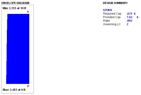
Envelope Diagrams
These diagrams show the axial forces
Note:
Design Summary
This portion gives you the capacity and strength values at the section in the wall where the combined check is maximum, as well as the governing load combination. Much of this information is also reported in the Wood Wall Panel Design spreadsheets.
Studs
The provided capacities of these members are calculated using the standard provisions for tension/compression members. These members are assumed to be fully braced in the weak axis, and unbraced in the strong axis. For more information on the chord force calculations, see the Wood Wall - Design topic.
Cross Section Detailing
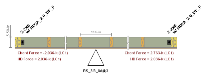
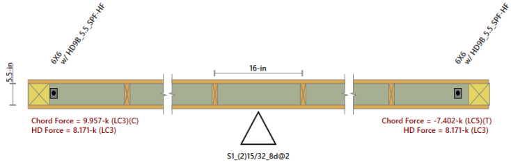
The last section of the detail report consists of the wall detailing information. This information is provided as a visual confirmation of the wall design. The wall thickness, and stud spacing are shown as dimensions. The chord sizes/forces and hold down or strap designations/forces are shown at either end.