One of RISAFloor’s primary tasks is the modeling, loading, and design of beams. This includes automatic attribution of loads from the deck system, live load reduction, and design optimization for the desired code and criteria. Loads modeled on the deck are attributed to the beams and the beams transfer the loads through the floor framing to walls and columns and ultimately down to the foundation. Automatic live load reductions may also be applied. With the use of beam end releases you may define simply supported or fixed end / continuous beams.
The beams can function to resist only gravity loads, where they are analyzed and designed completely within RISAFloor, or they can function as part of a lateral load resisting system. The lateral systems can be analyzed in RISA-3D for load cases such as wind or seismic events and the beams are designed for combined gravity and lateral forces. See RISA-3D Integration for more information.
Beam data may be viewed and edited in two ways: graphically in the Information Dialog or in the Beams Spreadsheet. See Beams – Primary Data for descriptions of the beam data.
Beams can be specified as Hot Rolled Steel, Cold Formed Steel, Wood, Concrete, and Steel or Wood on beam supported floors and as Concrete only on slab supported floors. Refer to the specific sections for Steel Design, Wood Design, and Steel or Wood Product Selection for more info on the design or code checking of beams. The shape groups available for each designation are listed below.
| Designation | Shape Group |
|---|---|
| Hot Rolled | Wide Flange |
| Channel | |
| Tube | |
| Single Angle | |
| Double Angle | |
| Pipe | |
| W_Tee | |
| Cold Formed | CU |
| CS | |
| ZU | |
| ZS | |
| HU | |
| Wood | Rectangular |
| Rectangular Double | |
| Rectangular Triple | |
| Round | |
| Glulam Western | |
| Glulam Southern Pine | |
| Concrete | Rectangular |
| Rectangular MM (metric dimensions) | |
| Steel Product | Steel Joist |
| Wood Product | Wood Joist |
| TJI Joist | |
| LPI Joist | |
| BCI Joist |
Any available material listed in the Materials spreadsheet can be assigned to a beam. See Material Properties for more information. All beam shapes and material properties may be assigned graphically either as you draw or later as a modification to the beams.
To create new beams you can draw from Point to Point, point to Beam, and Beam to Beam. Point to Point is when you want to draw a beam between columns, points, or a combination of column and a point. Point to Beam is when you draw a beam from a column or snap point to a beam with an offset distance from the beam end. Beam to Beam is when you draw between beams using an offset distance for both members. For Beam Offsets click toward the end of the member that you want the offset measured from. You can set all of the beam properties before drawing them or you can modify these properties after you draw a beam. Graphically modifying properties is discussed in the next section. See Beams– Primary Data for information on the beams and beam properties themselves.
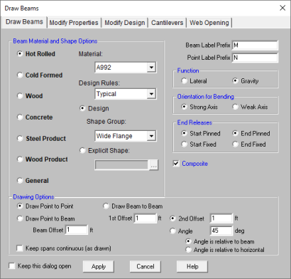
To draw beams, click ![]() on
the Drawing Toolbar to open the Draw Beams dialog. Enter
the beam type, material, shape group, redesign rules, span type, function,
orientation, end releases, and drawing option, click Apply and
draw beams accordingly.
on
the Drawing Toolbar to open the Draw Beams dialog. Enter
the beam type, material, shape group, redesign rules, span type, function,
orientation, end releases, and drawing option, click Apply and
draw beams accordingly.
As you draw, the coordinates of the nearest grid point or snap point are shown in the status bar in the lower right corner. The new beams will be shown on screen and will be recorded in the Beams spreadsheet.
 on the RISA toolbar to open a new view
and click
on the RISA toolbar to open a new view
and click  to turn on the Drawing
toolbar if it is not already displayed.
to turn on the Drawing
toolbar if it is not already displayed. button
and set the beam properties.
button
and set the beam properties. Click Apply to start drawing beams by clicking on columns, beams, or points with the left mouse button. For Beam Offsets click toward the end of the member that you want the offset measured from. The coordinates of the closest grid point or snap point to your cursor are displayed in the lower right hand corner.
The first click will define the Start-end of the first beam. The second click and each click thereafter will define the End-end of the first beam and also the Start-end of the next beam so that you may continue to draw as if your pencil is down. To pick up the pencil, click the right mouse button. You may then start drawing somewhere else with the left button.
Note
 button.
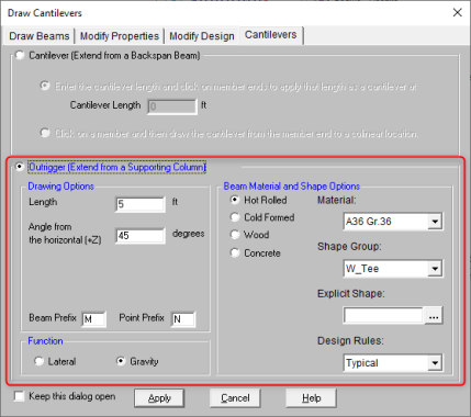
Cantilevers may only be drawn from existing beams. Use the Cantilever tool to extend a cantilever off of an existing beam.
Note:
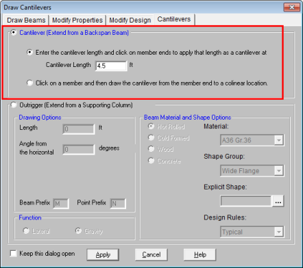
Outriggers may only be drawn from existing columns. Use the Cantilever tool to define and draw your outrigger member. Once drawn, the outrigger members will have the Outrigger check-box selected in the Beams spreadsheet to flag that they are outrigger members.
Note:
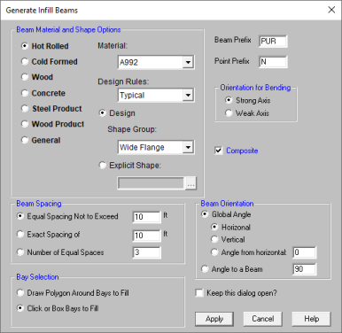
Because they tend to be evenly spaced and repetitive, you would not want to draw each and every one of your infill beams or joists. RISAFloor provides special tools on beam supported floors to generate large numbers of infill beams at one time. These tools will allow you to draw an entire bay of new infill beams with a single click. You can set all of the infill beam properties up front or you can modify these properties after you generate them. The procedure for graphically modifying infill beam properties is exactly the same as discussed in the previous sections.
To draw infill beams, click ![]() on the Drawing Toolbar to open the Generate
Infill Beams dialog. Enter the beam type, material, shape
group, redesign rules, orientation for bending, beam spacing, placement
orientation, and the bay selection option, click Apply and click
the bay to be filled. You can also draw a polygon around multiple
bays or simply drag a box around the bays to be filled. If the placement
orientation is referenced to a global angle then no other clicks are required,
the new beams will be shown on screen and will be recorded in the Beams
spreadsheet. If the placement orientation is referenced to a member
you must then click the reference member and the new beams will be created.
on the Drawing Toolbar to open the Generate
Infill Beams dialog. Enter the beam type, material, shape
group, redesign rules, orientation for bending, beam spacing, placement
orientation, and the bay selection option, click Apply and click
the bay to be filled. You can also draw a polygon around multiple
bays or simply drag a box around the bays to be filled. If the placement
orientation is referenced to a global angle then no other clicks are required,
the new beams will be shown on screen and will be recorded in the Beams
spreadsheet. If the placement orientation is referenced to a member
you must then click the reference member and the new beams will be created.
Note:
To Draw Infill Beams
on the RISA toolbar to open a new view
and click to turn on the Drawing
toolbar if it is not already displayed. button
and set the beam properties.
button
and set the beam properties. Note
button.For additional advice on this topic, please see the RISA Tips & Tricks webpage at risa.com/post/support. Type in Search keywords: Infill Beams.
There are occasions where your input infill beam spacing may not perfectly fit the bay selected. In these cases you will be presented with the Resolve Beam Choices dialog.
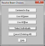
This dialog allows you to make a manual; choice between the available spacing options, rather than having the program randomly choose one. For example, if you have a 10' x 10' bay and you ask for an exact spacing of 3 ft, you will be presented with the two options:
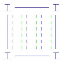
The green lines represent a 3 ft spacing starting from the left hand side, while the blue lines represent a 3 ft spacing starting from the right hand side. Rather than assuming one or the other, the program offers you the choice of where you want your framing located.
Choosing Centered in Bay will center the beams in the bay, and split the remaining space evenly on both sides.
There are two ways to modify beams. You may view and edit the beam data in the Beams Spreadsheet.Or, you can use the Modify Beams tool of the Beams dialog to graphically modify a possibly large selection of beams. See Beams – Primary Data for information on the beams and properties themselves.
The graphical Beam Modify tool discussed here lets you modify the properties of beams that already exist in your model. To use this, you will typically specify parameters you want changed then select the beams that you want to modify. You can modify beams one at a time by selecting the Click to Apply option and then click on the beams you wish to modify. You may also modify entire selections of beams by selecting the beams first and then use the Apply to Selected option. See Graphic Selection for more on selecting or unselecting portions of your model.
To Modify Beams
on the RISA toolbar to open a new view
and click to turn on the Drawing
toolbar if it is not already displayed. button
and select the Modify Properties tab. Set the parameters for the
changed beams. Check the Use? Box for the items to apply. You may choose to modify a single beam at a time or an entire selection of beams.
To modify a few beams choose Apply Entries by Clicking Items Individually and click Apply. Click on the beams with the left mouse button.
To modify a selection, choose Apply Entries to All Selected Items and click Apply.
Note:
button.The parameters shown are nearly the same as those used to define new beams.
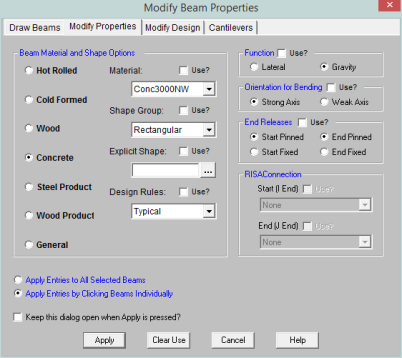
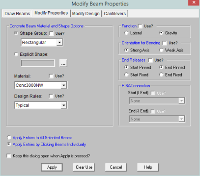
The Use? check boxes next to the data fields indicate whether the particular parameter will be used or not when the modification is applied. If the box next to a field is checked, that parameter will be applied to any selected beams. If the box is NOT checked, the parameter will NOT be applied, even if a value is entered in the field. This lets you easily change one or two properties on beams without affecting the rest of the properties. Note that if the field is blank and the corresponding Use? box is checked, clicking Apply will have the effect of clearing the data for these fields.
Note:
You can graphically specify the AISC, AISI, NDS and composite design parameters such as unbraced lengths, K factors, and effective widths. See Hot Rolled Steel - Design, Cold Formed Steel - Design, Wood - Design, Concrete - Design, and Hot Rolled Steel - Composite Beam Design for information on the design parameters themselves.
To do this, you will specify the appropriate beam parameters then select the beams that you want to modify, and then click on the Apply button. Alternately you can set the parameters and then choose the Click to Apply option, which allows you to then click on the beams you want modified.
To Modify Beam Design Parameters
on the RISA toolbar to open a new view
and click to turn on the Drawing
toolbar if it is not already displayed. button
and select the Modify Properties tab. Set the parameters for the
changed beams. Check the Use? Box for the items to apply. You may choose to modify a single beam at a time or an entire selection of beams.
To modify a few beams choose Apply Entry by Clicking Items Individually and click Apply. Click on the beams with the left mouse button.
To modify a selection, choose Apply Entries to All Selected Items and click Apply.
Note:
button.
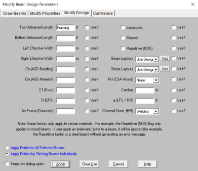
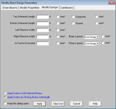
The Use? check boxes next to the data fields indicate whether the particular parameter will be used or not when the modification is applied. If the box next to a field is checked, that parameter will be applied to any selected beams, if the box is NOT checked, the parameter will NOT be applied, even if a value is entered in the field. This lets you easily change one or two properties on beams without affecting all the rest of the properties. Note that if the field is blank and the corresponding check box is checked, clicking Apply will have the effect of clearing the data for these fields.
Just as with the points you may double-click any beam member to view it’s properties. All of the same information that is stored in the Beams spreadsheet is displayed for the member you choose, and may be edited. This is a quick way to view and change member properties. For large selections of members however the spreadsheet and graphic editing tools may be the faster solution.
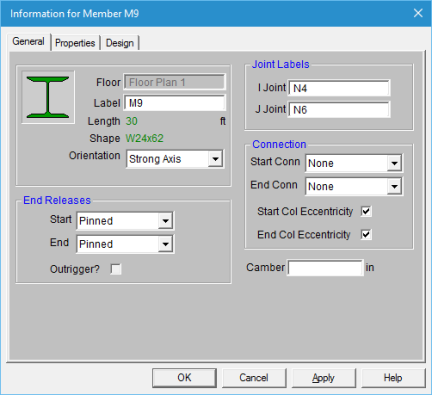
Floor Level - This displays the floor level that the beam is located on. This is not editable in this dialog.
Label - This allows you to view and modify the beam label.
Length - Reports the beam length.
Shape - Reports the beam shape.
Orientation - This allows you to view and modify the orientation of the beam (strong axis or week axis).
End Releases - This tab allows you to view and modify the end releases for each end of the member.
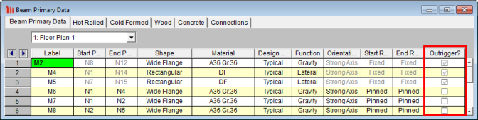
Outrigger - This check-box reports whether or not the member was originally drawn as an outrigger cantilever member. This is not editable in this dialog.
Joint Labels - This allows you to view and modify the end points of the beam.
Start/End Connection - This allows you to define Connection Rules for your hot-rolled steel connection design to be used in conjunction with RISAConnection. See the RISAConnection Integration topic for more information.
Col Eccentricity - This allows you to specify whether the eccentricity between the column centerline and the beam's end reaction resultant should contribute additional moment to the design of the column. This option is only available for pinned beam ends which frame into columns.
Camber - This allows you to view and modify the beam camber value.
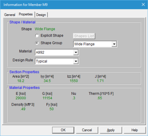
Shape/Material - This allows you to view and edit the shape properties. The associated Section Properties and Material Properties are reported below.
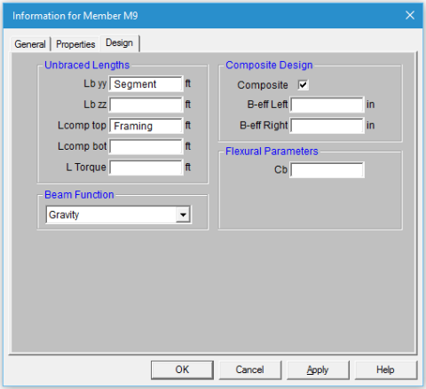
Unbraced Lengths - This allows you to view and modify the beam's unbraced length values. See the Unbraced Lengths topic for more information.
Beam Function - This allows you to view and modify the beam function.
Composite Design - This allows you to view and change the composite beam selections.
Flexural Parameters - This allows you to view and edit the flexural design parameters for member code check calculations.
The Beams spreadsheet records the properties for the beam elements and may be accessed by selecting Beams on the Spreadsheets menu. The spreadsheet has six tabs: Primary Data, Hot Rolled, Cold Formed, Wood, Concrete and Connections. The pull down list at the top of the spreadsheet allows you to toggle between floors.
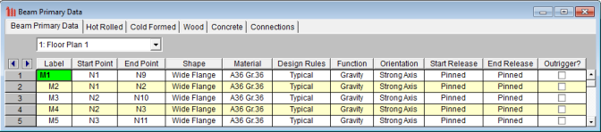
All beams for a particular floor are listed on the Beam Primary Data tab. You may choose the floor from the drop down list at the top of the spreadsheet. The Hot Rolled, Cold Formed, Wood, and Concrete tabs list only beams that use those materials.
The entries for the Beam Primary Data tab are explained below:
A unique label may be assigned to all of the beams manually or automatically. You can then refer to the beam by its label. You may relabel beams at any time with the Relabel Beams option on the Tools menu. The label column of the spreadsheet is displayed on all tabs of the spreadsheet.
Start Point and End Point list the labels of the start and end points of the beam. See Points for more information about points.
Enter the shape group and material you wish to use for the beam. You can choose both by clicking on the arrow in the cell. The material pull down list presents materials listed in the Materials spreadsheet. See Material Properties for more information.
A Shape Group (also known as a Design List) designates the type of beams that will be used to design and optimize the beam. Refer to Appendix A - Redesign Lists for more information.
Enter the set of design rules you wish to use to optimize the design of the beam. You can choose by clicking on the arrow in the cell. This pull down list is related to the Design Rules spreadsheet. See Design Optimization for more information.
The Function of a beam may be selected by choosing either 'Lateral' or 'Gravity' from the drop down list. Beams that are indicated as 'Lateral' will be designed for gravity loads in RISAFloor and may be optimized for lateral loads (and gravity loads) by RISA-3D. See RISA-3D Integration for more information.
Enter the orientation you wish to use for the beam – Strong Axis or Weak Axis. You can choose by clicking on the arrow in the cell.
Note
 button on the Window toolbar.
Releases control the forces that may be resisted by a beam. You may use these to define pinned connections, for simply supported gravity beams, or fixed connections. To specify beam releases go to the Start Release or End Release field for the beam and select the condition from the list.
This flag denotes whether or not the beam is an outrigger. This cannot be edited within the spreadsheet, it is only set when you draw in the outrigger using the Cantilever tool.
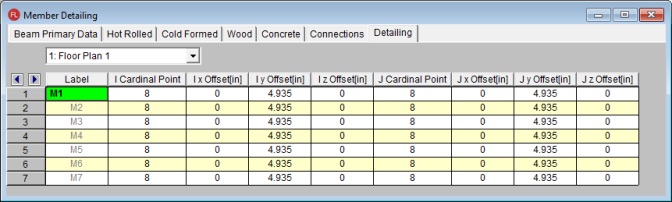
The Detailing tab records the detailing data for the beams that are necessary for full 2-way data transfer between RISA and steel detailing packages. For more information on this subject refer to the Help file for the RISA CIS/2 Translator which can be downloaded from our CIS\2 Translator Page on our website at risa.com.
Note: