Columns - Modeling
Both columns and walls may be used as supports for beams or concrete slab floors, and both transfer
load from floor to floor, and ultimately to the foundation. For beam-supported floors, column design is available for Hot
Rolled Steel, Cold Formed Steel, Wood, and Concrete. Only concrete columns may be used to support concrete slab floors. Automatic live load reduction for columns is available as well.
Columns may be defined as either Gravity columns or Lateral columns.
Gravity columns are analyzed and designed completely within RISAFloor for gravity/vertical loads only.
Lateral columns function as part of the lateral load resisting system
which can be analyzed and designed in RISA-3D for the combined gravity/vertical loads as well as lateral forces. See RISA-3D Integration
for more information on lateral system design.
Columns can be specified as Hot Rolled, Cold Formed, Wood, or Concrete.
The shapes available for each are listed below:
| Designation |
Shape Group |
|
Hot Rolled
|
Wide Flange
|
|
|
Tube
|
|
|
Pipe
|
|
|
Channel
|
|
|
Single Angle
|
|
|
Double Angle
|
|
|
W_Tee
|
|
|
WF 8
|
|
|
WF 10
|
|
|
WF 12
|
|
|
WF 14
|
| |
HSS Pipe |
| |
Square Tube |
|
Cold Formed
|
CU
|
|
|
CS
|
|
|
ZU
|
|
|
ZS
|
|
|
HU
|
|
Wood
|
Rectangular
|
|
|
Rectangular Double
|
|
|
Rectangular Triple
|
|
|
Round
|
|
Concrete
|
Rectangular
|
|
|
Rectangular Square |
| |
Round
|
| |
Rectangular_MM |
| |
Rectangular_MM Square
|
| |
Round_MM |
Any available material listed in the Materials spreadsheet can be assigned to a column (See Material
Properties). All column shapes and material properties may be
defined graphically as you draw or later using the Modify command.
Refer to the next two sections for more information.
Column / Beam Interaction
Columns may be modeled as vertical supports with no rotational stiffness,
or as vertical supports with a rotational stiffness based on their height,
section properties, and orientation. Refer to Model Settings - Solution for more information.
The fixity at the top of a column stack may be controlled through the Columns Spreadsheet.
Drawing Columns
New columns may be drawn in a model view window using a Project Grid,
Drawing Grid,
or previously entered point locations. You can set all of the column properties
before drawing them or you can modify the properties afterward.
Modifying properties is discussed in the next section.
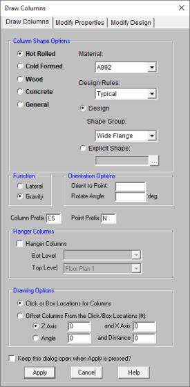
To draw columns, click  on
the Drawing toolbar to open the Draw Columns dialog. Enter
the column type, material, shape group, function, and orientation followed
by the drawing option you wish to use. By
selecting the Click or Box Locations for Columns option you will click
or box existing grids or points after clicking Apply.
Clicking on a grid intersection or point defines a single column.
By boxing multiple grid intersections you can define multiple columns
at once. Choosing
the Offset Columns From the Click/Box Locations option allows you to
define a horizontal and/or vertical offset or an angular offset from the
selected grid intersections or points. As
you draw, the coordinates of the nearest grid point are shown in the status
bar in the lower right corner. The new columns will be shown
on screen and will be recorded in the Columns and Column
Stacks spreadsheets.
on
the Drawing toolbar to open the Draw Columns dialog. Enter
the column type, material, shape group, function, and orientation followed
by the drawing option you wish to use. By
selecting the Click or Box Locations for Columns option you will click
or box existing grids or points after clicking Apply.
Clicking on a grid intersection or point defines a single column.
By boxing multiple grid intersections you can define multiple columns
at once. Choosing
the Offset Columns From the Click/Box Locations option allows you to
define a horizontal and/or vertical offset or an angular offset from the
selected grid intersections or points. As
you draw, the coordinates of the nearest grid point are shown in the status
bar in the lower right corner. The new columns will be shown
on screen and will be recorded in the Columns and Column
Stacks spreadsheets.
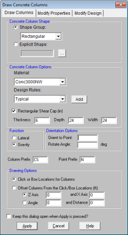
Beam Supported Floors:
Concrete Slab Floors:
- If
there is not a model view already open, click
 on
the RISA toolbar to open a new view and click
on
the RISA toolbar to open a new view and click  to turn on the Drawing toolbar if it is
not already displayed.
to turn on the Drawing toolbar if it is
not already displayed.
- If
you do not already have a grid or existing point locations available you
will need to create them first.
- Click
the
 button
and set the Column Shape, Material options, Design Rule, Function, Orientation, and Drawing Options.
button
and set the Column Shape, Material options, Design Rule, Function, Orientation, and Drawing Options.
- Click
Apply to start drawing columns by clicking or boxing grid intersections
and/or points with the left mouse button. The coordinates of the
closest grid or point to your cursor are displayed in the status bar on
the lower right hand corner of your screen.
- To
stop drawing altogether click the right mouse button, or press the ESC
key.
- Press CTRL-D to quickly
recall the dialog and make changes.
- You may also specify
or edit columns in the Columns or Column Stacks spreadsheets.
- Undo any mistakes
by clicking the Undo
 button.
- For information on modeling shear caps please see the Punching Shear - Design topic.
Below are steps to draw hanger columns. For more information, see Hanger Columns.
- If
there is not a model view already open, click on
the RISA toolbar to open a new view and click to turn on the Drawing toolbar if it is
not already displayed.
- Verify the floor from which the hanger columns will originate has been modeled.
- Create a new beam supported floor that is located beneath the floor where the hanger columns originate.
- Show the Plan View of the floor which the hanger column originates from (supporting floor) to draw the hanger column.
- Click
the button
and set the Column Shape, Material options, Design Rule, Function, Orientation, and Drawing Options.
- Turn on the checkbox for Hanger Columns and verify the bottom and top levels. Note that currently hanger columns can only be drawn from the supporting level to its adjacent level below, so users cannot use the dropdown to change the top and bottom levels of hanger columns.
- Click
Apply to start drawing columns by clicking anywhere along the length of the beam with the left mouse button. The coordinates of the
closest grid or point to your cursor are displayed in the status bar on
the lower right hand corner of your screen.
- To
stop drawing altogether click the right mouse button, or press the ESC
key.
- Hanger columns will collect floor loads from connecting beams and take them up to the supporting beams above as concentrated loads.
- Hanger columns can only support a single floor at this time.
- Hanger columns can only be Hot Rolled, Cold Formed, or Wood shapes.
- Hanger columns can only be drawn for Beam Supported Floors.
- Hanger columns cannot be supported by walls or columns from above or below.
- Hanger columns cannot be drawn from framing members that are supported by hanger columns.
- No outriggers are allowed on hanger columns.
Modifying Column Properties
To modify column properties you may edit the column data in the Columns
and/or Column Stacks spreadsheets. Use
the Modify Properties tab of the
Columns dialog to graphically
modify a large selection of columns at once. See Column
Primary Data for specific information on the column properties.
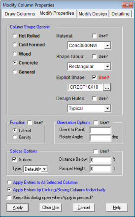
The graphical Modify Properties
tool lets you modify the properties of columns that already exist in your
model. To use this, you will typically specify the parameters you
want to change and then select the columns that you want to modify.
You can modify columns one at a time by selecting the Click to Apply
option and then clicking on the columns you wish to modify. You
may also modify entire selections of columns by previously selecting the
columns and using the Apply to Selected option. See Graphic
Selection for more information on selecting.
- If
there is not a model view already open, click on
the RISA toolbar to open a new view and click to turn on the Drawing toolbar if it is
not already displayed.
- Click
the
 button
and select the Modify Properties tab. Set the parameters for the columns
you wish to modify. Check the Use? box for each of the parameters
you wish to apply.
button
and select the Modify Properties tab. Set the parameters for the columns
you wish to modify. Check the Use? box for each of the parameters
you wish to apply.
- To modify columns one at a time choose Apply
Entries by Clicking Items Individually and click Apply.
Click on the columns with the left mouse button. To
modify a selection of columns, choose Apply Entries to All Selected
Items and click Apply.
- To modify more columns
with different parameters, press CTRL-D to recall the Modify Properties
settings.
- You may also modify
columns in the Columns or Column Stacks spreadsheets.
- Undo
any mistakes by clicking the Undo button.
The parameters shown are the same as those used to define new columns.
Beam Supported Floors:
Concrete Slab Floors:
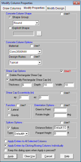
The Use? check boxes next to
the data fields indicate whether the particular parameter will be used
or not when the modification is applied. If the box next to a field
is checked, that parameter will be applied to any selected columns, if
the box is NOT checked, the parameter will NOT be applied, even if a value
is entered in the field. This lets you easily change one or two
properties on columns without affecting all the rest of the properties.
Note that if the field is blank and the corresponding Use?
box is checked, clicking Apply
will have the effect of clearing the data for these fields.
Modifying Column Design Parameters
To modify column design parameters you may edit the column data in the Columns spreadsheet. Use
the Modify Design tab of the
Columns dialog to graphically
modify a large selection of columns at once. See Columns Spreadsheet for specific information on the column properties.
The graphical Modify Design
tool lets you modify the design parameters of columns that already exist in your
model. To use this, you will typically specify the parameters you
want to change and then select the columns that you want to modify.
You can modify columns one at a time by selecting the Click to Apply
option and then clicking on the columns you wish to modify. You
may also modify entire selections of columns by previously selecting the
columns and using the Apply to Selected option. See Graphic
Selection for more information on selecting.
- If
there is not a model view already open, click on
the RISA toolbar to open a new view and click to turn on the Drawing toolbar if it is
not already displayed.
- Click
the button
and select the Modify Design tab. Set the design parameters for the columns
you wish to modify. Check the Use? box for each of the parameters
you wish to apply.
- To modify columns one at a time choose Apply
Entries by Clicking Items Individually and click Apply.
Click on the columns with the left mouse button. To
modify a selection of columns, choose Apply Entries to All Selected
Items and click Apply.
- To modify more columns
with different parameters, press CTRL-D to recall the Modify Properties
settings.
- You may also modify
column design parameters in the Columns spreadsheet.
- Undo
any mistakes by clicking the Undo button.
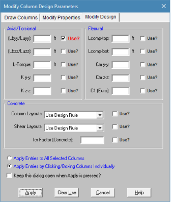
The Use? check boxes next to
the data fields indicate whether the particular parameter will be used
or not when the modification is applied. If the box next to a field
is checked, that parameter will be applied to any selected columns, if
the box is NOT checked, the parameter will NOT be applied, even if a value
is entered in the field. This lets you easily change one or two
properties on columns without affecting all the rest of the properties.
Note that if the field is blank and the corresponding Use?
box is checked, clicking Apply
will have the effect of clearing the data for these fields.
Column Stacks and Physical Columns
Each column modeled in RISAFloor is considered part of a Column Stack which occupies a particular "plan" location within the building model. Column Stacks consist of numbered Column Lifts or Physical Columns. A physical column or column lift may be continuous through one or more floor levels and are defined by Splice locations within the column stack. Column Stacks and Physical Column Lifts are defined on the Column Stacks spreadsheet.
Column Splices separate one physical column or column lift from the next within a column stack and can be defined as Moment Splices or Shear Splices. Moment Splices transfer both moment and shear from one physical column to the next. Shear Splices transfer only shear forces from one physical column to the next. Column Splices and locations may be assigned on the Columns spreadsheet or the Floors spreadsheet (defaults).
Columns may also be defined with Parapet extensions beyond the uppermost floor level. Parapets can only be applied to physical columns occurring along the perimeter of a deck/diaphragm area. Parapet Heights are defined on the Columns spreadsheet.
A particular column stack in a five story building consists of three column lifts or physical columns stacked one on top of the other. The column stack is tied to a particular plan location in building, regardless of elevation, and in this case occurs along the perimeter of the building.
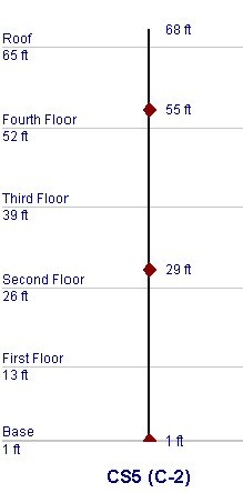
- Column Lift No. 1 is the lowermost physical column in the column stack and begins at the base elevation of the building and continues vertically to a moment splice whose elevation is defined by a distance measured 10 feet below floor level three.
- Column Lift No. 2 begins at the splice defining the top of Column Lift No. 1 (10 feet below floor level three) and continues vertically to a moment splice whose elevation is defined by a distance measured 10 feet below floor level five (the roof in this case).
- The uppermost physical column, Column Lift No. 3, begins 10 feet below floor level five and continues vertically to a parapet height measured 3 feet above floor level five (roof). The definition of a parapet is only allowed because the column is on the perimeter of the building.
For additional advice on this topic, please see the RISA Tips & Tricks webpage at risa.com/post/support. Type in Search keywords: Column Splices.
Columns Spreadsheet
The Columns spreadsheet contains all column input data, including primary data and material specific design parameters, and is floor level specific. The Floor Level may be selected from the pull down list just above the spreadsheet.
Primary Data
The Column Primary Data tab
of the Columns spreadsheet records the properties for the column
elements and may be accessed by selecting Columns on the Spreadsheets
menu. For
information on the Steel/Wood and Concrete
tabs, please refer to the Hot
Rolled Steel - Design, Cold
Formed Steel - Design, Wood
- Design, and Concrete -
Design sections. For information on shear caps view the Punching Shear - Design topic.
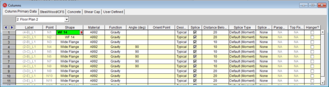
The entries for the Column Primary Data are explained below:
Label
Each column is assigned a label based on the corresponding Stack Label from the Column Stacks spreadsheet. That stack label is repeated here on the Columns spreadsheet with an extension, "_L#", that indicates the lift number for the particular column. The label field may not be edited on this spreadsheet but the stack label may be edited on the Column Stacks spreadsheet.
Point
The column location is defined by a point in the plane of the floor.
These points are created automatically as you draw the columns.
Shape & Material
Enter the Shape Group and Material you wish to use for the column.
You can choose both by clicking on the  arrow in the cell. The material
pull down list corresponds to the Materials spreadsheet. For more information, see
Design Optimization - Design
Lists or Material
Properties for more information. Any entry or editing in these cells will also apply to the Shape and Material entries on the Column Stacks spreadsheet.
arrow in the cell. The material
pull down list corresponds to the Materials spreadsheet. For more information, see
Design Optimization - Design
Lists or Material
Properties for more information. Any entry or editing in these cells will also apply to the Shape and Material entries on the Column Stacks spreadsheet.
Function
Enter the Function you wish to use for the column – Gravity or Lateral.
You can choose by clicking on the pull down list in the cell. Any entry or editing in this cell will also apply to the Function entry on the Column Stacks spreadsheet.
Angle
RISAFloor uses two methods to explicitly set the orientation of a column.
The first is by setting the angle of rotation for the column about vertical
global axis. Use the Angle (deg) entry to enter the rotation
angle you wish to use for the column. If the entry is left blank
or an angle of “0” is entered, the column is oriented so that the web
is "vertical" or "north/south" in the plan view.
The second orientation method is defined by the Orientation Point as
described below.
Orientation Point
The second method to explicitly define the orientation of a column is
by specifying an Orientation Point for the column. When used,
this orientation point and the column point form a line that defines the
orientation of the column web.
- You can combine the
Angle (deg) and Orientation Point to rotate the column with
respect to its orientation point.
Design Rules
Enter the Design Rules you wish to use for the column. Select from any custom input entered in the Member Design Rules spreadsheet.
Splice
The Splice check box indicates
whether there is a splice point in the column stack between the current
floor level and the floor level below. The
Splice check box will automatically
be checked at the lowest floor level of each column stack, indicating
the boundary condition of the column base.
- The RISA-3D Boundary conditions at the bottom of a column will be initially set to perfectly pinned or perfectly fixed based on the splice type in RISAFloor. However, after the initial creation of the 3D model, the splice type is no longer linked to the 3D and it is the user's responsibility to update their boundary conditions to reflect any changes to the base fixity that are initiated in RISAFloor. For additional advice on this topic, please see the RISA Tips & Tricks website: www.risa.com/post/support. Type in Search keywords: Column Boundary Conditions.
Distance Below (Splice Location)
The Distance Below entry indicates
the dimension to a splice located between the current
floor level and the floor level below. If
the splice check box is checked, the splice elevation will default to
the dimension defined in the Splice Distance Below
column of the Floors spreadsheet
for the current floor level. If
you wish to override the default splice dimension defined on the Floors Spreadsheet you may do so by
entering an explicit value here. These entries can also be edited via the Bot El. and Top El. entries on the Column Stacks spreadsheet.
It
is not possible to enter a negative dimension for the splice location as all entered values are considered as absolute values.
If you
would like to define a splice above the current floor level, you will
need to enter the splice on the floor level above. The
appropriate units are listed at the top of the column.
In the bottom column of a given column stack the Distance Below also defines the distance below the current floor elevation to the base of the column.
Note that in models with sloped floors, the distance below is always taken from the floor elevation regardless of the top elevation of a column.
For additional advice on this topic, please see the RISA Tips & Tricks webpage at risa.com/post/support. Type in Search keywords: Building on a Hill.
Note:
- The distance below may not be set less than 1 inch. This is to prevent divide by zero errors when resolving column moments into shears.
Splice Type
The Splice Type entry defines
the splice as either a Moment splice which will transfer moment and shear
between column lifts in the stack or a Shear splice which will only transfer
shear between lifts. If
the splice check box is checked, the splice type will default to the type
defined in the Splice Type column
of the Floors spreadsheet for
the current floor level. If
you wish to override the default splice type you may do so by selecting
a type from the pull down list in the cell in the Columns spreadsheet.
Splice Connection
The Splice Connection entry defines
the splice connection rule. Only column splice type connections may be applied at upper floors and only baseplate connection types may be applied at the bottom-most floor level. These connections can then be exported into RISAConnection for connection design.
Parapet Height
If the upper most lift of a column stack exists along the perimeter
of a diaphragm/deck, the user may assign a Parapet
Height to that lift indicating the dimension to the top of the
column with respect to the current floor level. This
"column extension" will be included in the floor tributary mass
or area for seismic and wind load generation respectively. The
default parapet height is deflned in the Floors spreadsheet.
- This field can not be edited for slab floors. The Default Parapet Height entry on the Floors spreadsheet defines the parapet for slab levels.
- Parapet height for wind considerations changed between V10.0.1 and V11 of RISAFloor. For the current behavior please see the Load Generation - Wind Loads topic.
- Parapets created with columns only have self-weight due to the parapet height of the columns extending up. The parapet itself has no self-weight.
Top Fixity
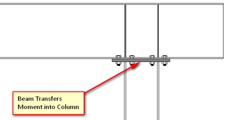
The entry controls how the column connects to beams which frame into the top of it. When the top of the column is set to Fixed, it will provide rotational restraint for any beams which are framed into it and which also have a fixed end condition. If either the column top or the beam end is set to pinned then no rotational restraint is provided. The primary purpose for this feature is to allow continuous beams to cantilever over the top of a column without transferring any moment into that column (see below)
In the situation illustrated below the column top should be set to Pinned:
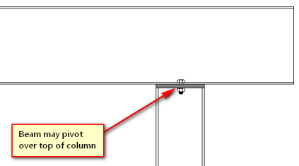
In the situation illustrated below the column top should be set to Fixed:
This setting is only available for the top column in the stack. All columns below the top floor for that column stack show "N/A".
Note:
- When setting the Column Top to be Pinned, the column will also ignore any moment that would be caused due to column eccentricity on shear connections.
- There must be a diaphragm present at the level where the top of column terminates to be able to define a pin at these locations.
- If a parapet is defined on this column then the column top must be fixed.
Hanger
This column indicates whether or not the column is a standard column or hanger column. If the entry is checked, it signifies the column is a hanger column.
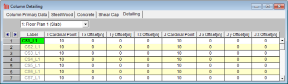
Columns Spreadsheet - Detailing Data
The Detailing tab records the detailing data for the columns that are necessary for full 2-way data transfer between RISA and steel detailing packages. For more information on this subject refer to the Help file for the RISA CIS/2 Translator which can be downloaded from our website.
Column Stacks Spreadsheet
The Column Stacks spreadsheet
contains summary information for all column stacks within the building
model and may be accessed by selecting Column
Stacks on the Spreadsheets
menu. When a column is drawn in RISAFloor, or added to the Columns spreadsheet, a Column Stack is automatically generated in the Column Stacks spreadsheet.
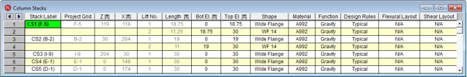
The entries for the Column Stacks spreadsheet are explained below:
Stack Label
When a column stack is created in RISAFloor, a Stack Label is automatically generated containing the column stack number and the corresponding project grid line intersection, CS1 (A-1) for example. You may overwrite this assigned label with a unique label of your own if you so choose. However, each
label must be unique, so if the same label is entered more than
once an error message will be displayed.
Project Grid
The values listed indicate the project grid lines on which the column
stack is located. These
values are not available for editing in this spreadsheet but may be adjusted
via the Label entries on the Project Grid Spreadsheet. If
a column stack is not located on a project grid line in a particular direction
a "?" will be used in place of a project grid line. If
a project grid line is added at the column stack location at a later time,
the Project Grid value will automatically
be updated to reflect the new project grid line.
Column Stack Coordinates
The column stack coordinates, Z
and X, contain the coordinates
of the Points in the horizontal
and vertical directions, respectively, that define the location of the
column stack. These values represent the offsets of the Points
from the origin of the global coordinate system (0, 0) and are not available
for editing in this spreadsheet but may be adjusted via the entries on
the Point Locations spreadsheet.
The appropriate units are listed at the top of each column.
Lift Number
Each physical column within a column stack is assigned a Lift
Number based on its location within the column stack. Lift
No. "1" is assigned to the lowermost physical column within
a column stack with Lift No. "2" assigned to the next physical column and so on, ascending from the bottom of the column stack to the top. These
values are not available for editing.
- There may be a "gap" in a column stack where no column occurs in the building plan at certain floor levels. The lifts will still be numbered sequentially from bottom to top. If the "gap" is later filled, the new physical column will merge with the column below unless an additional splice is added to the column stack. In which case, the column lifts will automatically be renumbered from bottom to top in order to account for the new lift and maintain sequential numbering.
Lift Length
The Length of each physical
column or "lift" is listed here. This
is the length of the column from the column base to a splice or top of
column, or from splice to splice, or splice to top of column, depending
on the position of the lift within the column stack. These
values may be editing in two ways. The first is by editing the Bottom and Top Elevation entries that follow in the Column Stacks spreadsheet and the second is
via the Distance Below entries
on the Column Primary Data tab
of the Columns spreadsheet.
Bottom/Top Elevation
The elevation of the bottom and top of each lift, Bot
El. and Top El. respectively,
are listed here with respect to the base elevation of the model. These
elevations are determined by the Distance Below entries as defined on the Column
Primary Data tab of the Columns
spreadsheet. These elevation entries may be edited and will subsequently update the appropriate entries in this and other spreadsheets.
Shape & Material
Enter the Shape Group and Material you wish to use for the column.
You can choose both by clicking on the arrow in the cell. The material
pull down list corresponds to the Materials spreadsheet. See
Design Optimization - Design
Lists or Material
Properties for more information. Any entry or editing in these cells will also apply to the Shape and Material entries on the Columns spreadsheet.
Function
Enter the function you wish to use for the column – Gravity or Lateral.
You can choose by clicking on the pull down list in the cell. Any entry or editing in this cell will also apply to the Function entry on the Columns spreadsheet.
Design Rules
A Design Rule may be applied to each lift of a column stack by making a selection from the pull down list in this cell. The available entries in the pull down list are created on the Design Rules spreadsheet. For more information see Design Optimization - Design Rules.
Rebar Layouts
For concrete columns, the Flexural Layout and Shear Layout entries may be used to assign a custom rebar layout to each lift of a column stack. A custom rebar layout must be used if the user would like to take advantage of bundled bars, multiple layers or reinforcement, or an unequal number of bars per face.
Custom rebar layouts are created in the Rebar Layout Database and may be selected from the pull down list in this spreadsheet once they have been created. If Optimize is selected from the pull down list, RISAFloor will perform the design and select the appropriate reinforcement for the column lift based on the selected design rule. The program will design for an equal number of bars in each face of a rectangular column (a minimum of four (4) bars will be used in circular column sections) and may vary that reinforcing
based on ACI minimums and maximums and the moment and shear demand at each
section along the span. If the material used for a column lift is not a concrete material, the entry will default to N/A.
See the Concrete Database section and the Rebar Layout Database for more information.
Column Stack Manager
The Column Stack Manager may be accessed from a model view by double-clicking any column. This window allows for the display and editing of the entire column stack as well as the coordinates of the application point. It is particularly useful for assigning or moving splices.
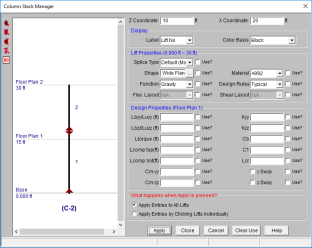
Display and Display Controls
The column stack manager will display the entire height of the column stack. The Label and the Color Basis of the window can be modified by selecting the appropriate setting using the drop down menus. Click Apply to accept any display changes.
The column display view on the left is interactive. If the user clicks on the column within the display window, the assigned column properties will be displayed in the text boxes on the right hand side. This is useful for confirming design properties on a lift by lift or floor by floor basis.
In the upper left hand corner of the column stack display window, there exists a number of icons that allow the user to edit the column and column splice data. These allow the user to Add, Delete, or Move a column splice. Similarly, the user may delete an entire column lift if desired. The last icon controls the increment at which a splice can be moved.
- When moving a splice it is only possible to move it within the height of the existing floor level. If the splice needs to be moved to a different level, then it should be deleted and a new splice added at the appropriate location.
- Moment splices are indicated by displaying a red diamond shape at the splice location.
- Shear splices are indicated by displaying a green circle at the splice location.
- The lowest level of the column splice indicates the boundary condition at the bottom of the column.
Lift Properties
In display mode, the Lift Properties section displays the start and ending point of the lift along with all of the basic lift properties. The starting and ending distance are only
In modify mode, the user can choose to modify column lifts one at a time by choose Apply
Entries by Clicking Items Individually and click Apply.
Click on the lift with the left mouse button. To
modify all of the displayed columns, choose Apply Entries to All Lifts and click Apply.
The Use? check boxes next to the data fields indicate whether
the particular parameter will be used or not when the modification is
applied. If the box next to a field is checked, that parameter will
be applied when the Apply button is pressed. If the box is NOT checked, the parameter
will NOT be applied, even if a value is entered in the field. This
lets you easily change one or two properties on a lift without affecting
all the rest of the properties.
- When moving a splice it is only possible to move it within the height of the existing floor level. If the splice needs to be moved to a different level, then it should be deleted and a new splice added at the appropriate location.
Design Properties
In display mode, the Design Properties section displays the current floor level along with all of the design parameters associated with this floor level.
In modify mode, the user can choose to modify column properties one floor at a time by choose Apply
Entries by Clicking Items Individually and click Apply.
Click on the floor, or slightly below it with the left mouse button. To
modify all of the displayed floor levels, choose Apply Entries to All Lifts and click Apply.
The Use? check boxes next to the data fields indicate whether
the particular parameter will be used or not when the modification is
applied. If the box next to a field is checked, that parameter will
be applied when the Apply button is pressed. If the box is NOT checked, the parameter
will NOT be applied, even if a value is entered in the field. This
lets you easily change one or two properties on a lift without affecting
all the rest of the properties. Note that if the field is blank
and the corresponding Use? box is checked, clicking Apply
will have the effect of clearing the data for these fields.