Elevated slab analysis and design is done with RISAFloor ES. A slab must be defined that will then be loaded and analyzed. At solution the program will create a finite element mesh of plates to represent the slab. From there an analysis is considered and the program will then design the slab based on design strips.
Note
Slab edges and must be defined to establish the extents of the slab. Properties for the slab are defined in the Slab Definitions spreadsheet.
To create slab edges or openings click ![]() on the Drawing Toolbar to open the Draw Slabs dialog.
on the Drawing Toolbar to open the Draw Slabs dialog.
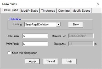
Enter the Slab Definition you want to use or create a new one by pressing the New button.
Here is where to define the properties of the slab. See the Slab Definitions spreadsheet information below for more information.
To Draw a Slab
Note
To modify slabs edges click ![]() on the Drawing Toolbar and click on the Modify Slabs tab.
on the Drawing Toolbar and click on the Modify Slabs tab.
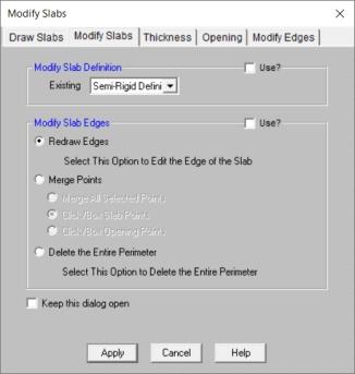
This will allow you to click on a slab graphically to change itsSlab Definition. The Slab Definition defines the type of slab, thickness and loading. Refer to the Slab Definitions spreadsheet for more information.
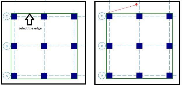
This option will let you take individual edges of the slab and re-draw them to a different geometry than they were individually drawn. This tool works on one entire straight line edge. The first step is to click on the edge you want to modify and then the cursor will be attached to the starting point of that edge with a red line. You can continue to click on any number of points to redefine this edge and the final click should end at the original end point of the edge.
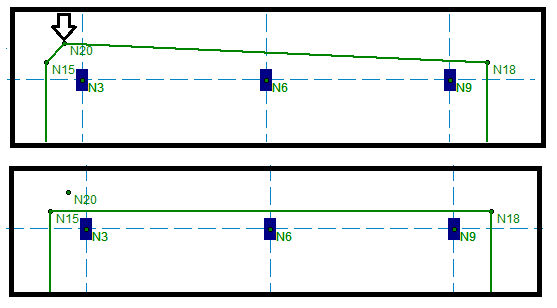
This option allows you to remove a point or node from the slab edge. Below is an example of a corner defined by two points. Selecting Merge Points and clicking on N20 removes that point from the slab edge. This tool can be used in conjunction with the Redraw Edges to redefine the slab edge if it's draw incorrectly. This tool can be used on the slab edges or you can use it for the openings.
This option can be used to remove the entire perimeter so that it can be re-drawn. Select this option and you can then click on any edge in the model and it will be deleted.
Note
 button.
The slab thickness can be adjusted anywhere within a slab. The slab thickness will affect the design of the slab including design strip reinforcement design, punching shear and the FEA plate thickness.
To modify slabs thickness, click ![]() on the Drawing Toolbar and click on the Thickness tab.
on the Drawing Toolbar and click on the Thickness tab.
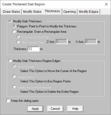
Click Point to Point to define a polygon of any size or shape by selecting three or more points.
To define a rectangular shape of any size, first click is the one corner, then stretch the mouse to create the desired size and the second click is the diagonal opposite corner.
To define a rectangular shape of any size, define the size of the rectangular in the Z and X axis and then click the center point.
To move the corners of thickened region(s).
To remove the corners of thickened region(s).
To delete thickened region(s).
Note:
To add openings to slabs click ![]() on the Drawing Toolbar and click on the Opening tab.
on the Drawing Toolbar and click on the Opening tab.
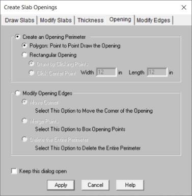
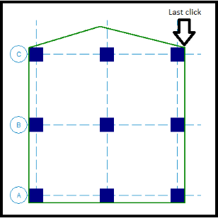
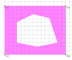
You can create an opening of any shape by selecting points to form a polygon shape. Click twice on the last point to indicate that the polygon is complete. Below shows an opening with a polygon shape.
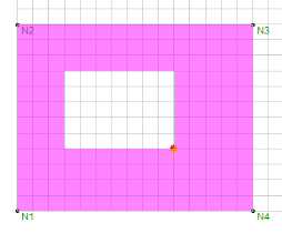
You can create a rectangular opening of any size by selecting two points to form the rectangle. The first click is the one corner, then stretch the mouse to create the desired size and the second click is the diagonal opposite corner. Below shows a rectangular opening.
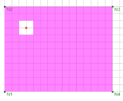
You can create a rectangular opening of a desired size by clicking in the center of the opening. The dimensions entered are the overall dimensions of the opening. Below shows the center point (red dot) with Z axis dimension of 24 in and X axis dimension of 24 in.
To move the corners of opening(s).
To remove the corners of opening(s).
To delete opening(s).
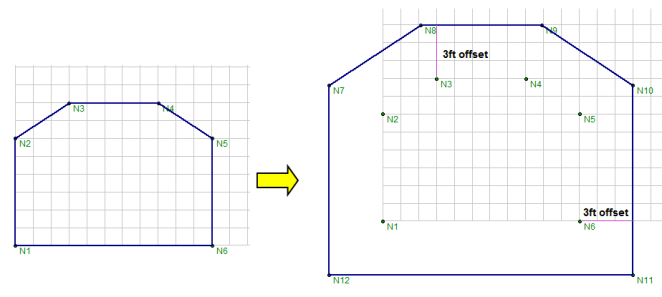
To offset a slab click ![]() on the Drawing Toolbar and click on the Modify Edges tab. This tool allows you to enlarge or minimize the size of a slab using an distance offset by entering a offset distance and clicking on the slab to be offset. You can input a positive number to enlarge the slab or a negative number to minimize the slab.
on the Drawing Toolbar and click on the Modify Edges tab. This tool allows you to enlarge or minimize the size of a slab using an distance offset by entering a offset distance and clicking on the slab to be offset. You can input a positive number to enlarge the slab or a negative number to minimize the slab.
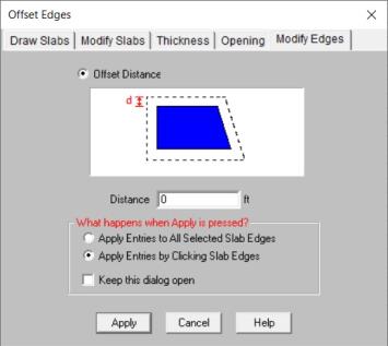
For example, if you indicate a 3 ft offset distance the slab edges will be offset linearly by 3 ft on all sides.
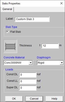
The Slab Definitions spreadsheet records slab properties and may be accessed by selecting Slab Definitions on the Spreadsheets menu. The spreadsheet has two tabs: General and Loads.
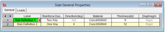
The General tab holds the general data for the slabs. The Loads tab contains self-weight and other load information for the slab.
Note:
A unique label may be assigned to all of the slab definitions manually or automatically. You can then refer to the slab definition by its label. You may relabel the slab definition at any time without affecting the application of the properties to the model.
This defines whether the design is a Two-Way slab design or One-Way slab design. The One-Way model behavior is very different than Two-Way slab, see One-Way Slab Design for more information.
When choosing a One-Way slab design, then a default direction of the span of the slab must also be defined. This direction can be overwritten with theSet One-Way Slab Propertiesbutton in the drawing toolbar. See One-Way Slab Design for more information. If you choose Two-Way slab design, this column doesn't apply.
This defines which concrete material is being used for the slab definition.
This defines the thickness of the slab.
This defines a Semi-Rigid or Rigid diaphragm in RISA-3D. Semi-Rigid can only be used with Two-Way Slabs. For more information on these options see the Diaphragms topic.
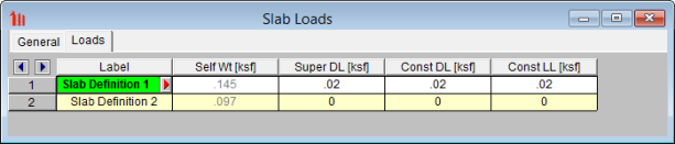
The Loads tab holds all the load data for the slab.
Self Weight is the weight of the slab system. This weight will be used as part of the pre-composite dead load (PreDL) and also as part of the post-composite dead load (DL) when creating load combinations for solution.
The Superimposed Dead Load (Super DL) is additional load that will be treated as additional slab self weight. This might be useful to account for deck topping or flooring materials that will be part of the dead load of the floor system. This load will be included for any calculations that include deck self weight is included (seismic mass, beam camber and any places the refer to load categories DLPre and DL).
You may define construction dead load that occurs during construction but is not part of the final load on the system. This weight will be used as part of the pre-composite dead load (PreDL) but not included as part of the post-composite dead load (DL) in the load combinations for solution.
You may define construction live load that occurs during construction but is not part of the final load on the system. This weight will be used as part of the pre-composite live load (LLConst) but not included as part of the post-composite live load (LL) in the load combinations for solution.
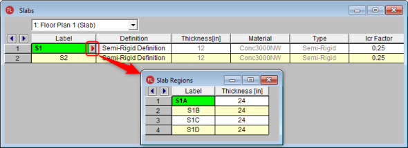
All elevated slabs will show up in the Slabs spreadsheet on a per floor basis. Here you can update the Slab Definition and the Icr Factor.
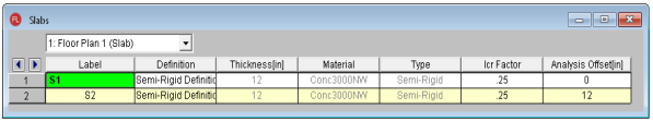
If you click the triangle button next to a slab Label, there is a separate spreadsheet to show all the slab regions for the current slab. You can modify the Label, and Thickness for each slab region.
The Icr Factor is used to reduce the bending stiffness of slabs per ACI 318-14 Section 6.6.3.1.1 (ACI 318-11 Section 10.10.4.1). This value defaults to 0.25.
Note