Slabs
In this section, we will describe how to draw a slab and how RISAFoundation handles the automatic generation of finite element plates. For information about reinforcement design for slabs, see Slabs - Design Strips and Slabs - Design Cuts.
Draw Slabs
You can draw slabs using a Drawing Grid, Project Grid or by clicking on existing nodes. You can set your slab properties up front, or you can modify these properties after drawing a slab.
You may define the slab by drawing a polygon that defines the entire slab. Or, you may draw multiple polygons that each define a smaller portion of the slab. If the border of your slab region aligns with another slab, both will be fully connected as if they were a single slab element. See the Automatic Slab Meshing section for a discussion on how the slabs are meshed.

Click on image to enlarge it
To create a Slab:
- If there is not a model view already open, go to the View ribbon.
- Click the Open 3D Views icon in the Window section to open a new view.
- Go to the Home ribbon.
- Click the Slabs icon in the Slab Elements section.
-
In the Properties panel, set the slab properties.
-
Start drawing a polygon to define slab region. To indicate that you have finished drawing the region, double-click on the last node of the polygon.
To stop drawing, click the right mouse button or press the Esc key.
Circular Slab Generator
The Circular Slab Generator allows users to quickly lay out a circular mat slab for design. Within the generator are options to include circular line loads and area loads so that you can automatically create your typical loading for round structure such as tanks.

Click on image to enlarge it
To create a Circular Slab:
- If there is not a model view already open, go to the View ribbon.
- Click the Open 3D Views icon in the Window section to open a new view.
- Go to the Home ribbon.
- Click the Circular Slabs icon in the Slab Elements section.
The Circular Slab Generator dialog displays, shown below:

Click on image to enlarge it
-
Enter the Polar Origin and Slab Properties information.
-
Select the Strip Along Z Axis (Plan Horizontal) and/or Strip Along X Axis (Plan Vertical) check boxes to have Design Strips automatically added to the slab for each respective direction.
-
Click Apply and the dialog closes. The circular slab will display in your 3D View.
-
Adjust properties as needed in the Properties panel.

Modify Slab Properties
There are a number of ways to modify slabs. You can view and edit the slab data in the Slabs Spreadsheet, which can be accessed by selecting Slabs from the Data Entry drop-down on the Spreadsheets tab of the ribbon, or by clicking Slabs from the Data Entry section of the Explorer panel. You may also select a slab (or multiple slabs) to view and edit the properties in the Properties panel. Here you can adjust the material, thickness, local axis angle, analysis offset, passive pressure, soil overburden and Icr factor. Clicking the  (ellipses) button within the Material input of the Properties panel or Slabs Spreadsheet will open the Review or Change Material dialog, where you can modify the element's material properties.

Click on image to enlarge it
To modify a Slab:
- If there is not a model view already open, go to the View ribbon.
- Click the Open 3D Views icon to open a new view.
- Click a single slab, or select multiple slabs that you wish to modify.
- If you have multiple elements selected, specify which element type to view properties for by using the Selection Properties drop-down in the Properties panel.
-
Set the parameters for the slab(s) within the Properties panel.
- For more information on the Local Axis Angle, see the Local Axis Angle section.
- For more information on the Passive Pressure, see the Passive Pressure section.
- For more information on Soil Overburden, see the Soil Overburden section.
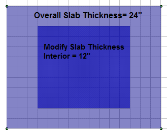
Draw Thickened Regions
You can draw Thickened Regionswithin the interior of an existing slab element to capture changes in slab thickness.

Click on image to enlarge it
To draw a Thickened Region within a slab:
- If there is not a model view already open, go to the View ribbon.
- Click the Open 3D Views icon in the Window section to open a new view.
- Go to the Home ribbon.
- Click the Thickened Regions icon in the Slab Elements section.
-
In the Properties panel, set the slab region thickness and choose a drawing option for creating the region.

Click on image to enlarge it
-
Start drawing a polygon to define a slab region. If drawing using the Node to Node option, double-click on the last node to indicate that you have finished drawing the region.
To stop drawing, click the right mouse button or press the Esc key.

Modify a Thickened Region

Click on image to enlarge it

Click on image to enlarge it
To modify Slab Thickness Region Edges:
- Go to the Modify ribbon.
- Click the Modify Thickness icon in the Slabs section.
-
In the Properties panel, select the Modification drop-down and choose between Move Corner, Merge Points and Delete the Entire Perimeter.
-
Click on the corners of the thickened region you wish to modify in the 3D View window, or click anywhere along the thickened region perimeter if you selected the Delete Entire Perimeter Option.
Modify Edges
There are several options available for modifying your overall slab geometry in the Slabs section of the Modify Ribbon.

Click on image to enlarge it
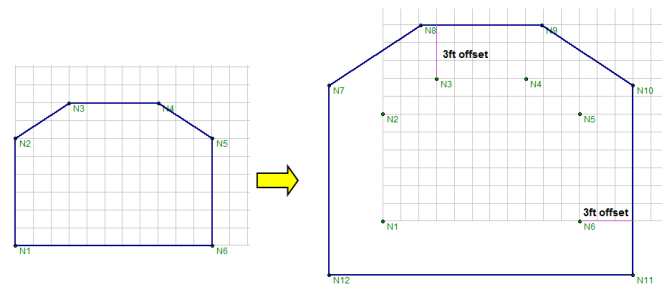
Offset Distance - Allows you to increase or decrease your slab edges by a fixed distance. Enter a positive number to enlarge the slab and a negative number to shrink the slab footprint. For example, if you indicate a 3 ft offset distance, the slab edges will be offset linearly by 3 ft on all sides.
Redraw Edges-Allows you to redefine the locations of individual slab edges.
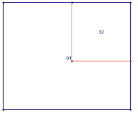
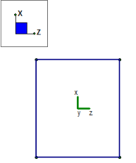
Edge Fixity - Adjusts the slab edge fixity to an adjacent slab element. This is useful for slabs that are not monolithically placed, where a shear key or dowels are used to transfer forces out-of-plane to the slab. By default, slab edges are fixed to each other when two adjacent slabs touch each other. Pinned slab edges are graphically indicated with a salmon color, as opposed to the typical blue slab edge. In the example below slab S2 is pinned along both edges that it shares with slab S1:
Remove Edge Points - Deletes the corner of a slab and connects the two adjacent points at the slab perimeter.
Delete Perimeter - Allows you to deletes the entire slab perimeter from the model.
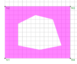
Create Slab Openings
The Slab Openings tool can be used to create an opening in an existing slab in your model.

Click on image to enlarge it
To create Slab Openings:
- Go to the Home ribbon.
- Click the Openings icon in the Slab Elements section.
-
Select the Draw Option in the Properties panel from the following:
-
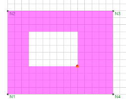
Node to Node - Click individual nodes to define an opening of any shape. double-click on the last node of the polygon to indicate that you have finished drawing
-
Rectangular Node to Node - Create a rectangular opening by clicking to define opposite corners of the opening.
-
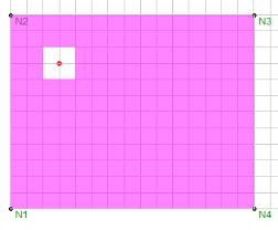
Rectangular Center Node - Enter the overall dimensions for the length and width of a rectangular opening and then click to define the center of the opening. The image below shows the center point (red dot) with Z-axis dimension of 24 in and X-axis dimension of 24 in.
-
-
Draw the opening based on the selected draw option. If Node to Node is selected, your opening.
To stop drawing, click the right mouse button or press the Esc key.
- Slab openings can be drawn in contact with the edge of the slab.
- Line loads and area loads will not be considered in the analysis of the slab if they are within the perimeter of an opening.
Modify Slab Opening Edges

Click on image to enlarge it

Click on image to enlarge it
To modify Slab Opening Edges:
- Go to the Modify ribbon.
- Click the Modify Openings icon in the Slabs section.
-
In the Properties panel, select the Modification drop-down and choose between Move Corner, Merge Points and Delete the Entire Perimeter.
-
Click on the corners of the slab opening you wish to modify in the 3D window, or click anywhere along the opening perimeter if you selected the Delete Entire Perimeter Option.
Slabs Spreadsheet
The Slabs Spreadsheet records the properties of each slab and may be accessed by selecting Slabs from the Data Entry drop-down on the Spreadsheets tab of the ribbon, or by clicking Slabs from the Data Entry section of the Explorer panel.

Click on image to enlarge it
The following data columns hold the primary data for the slabs:
Label
You may assign a unique label to each slab. Each label has to be unique, so if you try to enter the same label more than once, you will get an error message.
Thickness
This entry designates the thickness of the slab.
Material
This entry defines the concrete material that will be used for the properties of the slab. You can select the (ellipsis) button to open the Review or Change Material dialog, where you can modify the element's physical properties.
Local Axis Angle
This angle defines the orientation for sliding and overturning checks for slabs. By default, this value is set to 0 and will provide sliding and overturning checks about the global axes.
However, if you have a slab that is skewed from the global axes, then you may wish to have the overturning and sliding checks taken about those different axes.
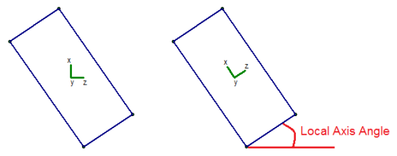
The results for sliding and overturning for slabs are then based on these local axes coordinates. For example, Mo-xx is the demand overturning moment about a slab's local x axis.
- The Local Axis Angle must be between 0 and 90.
- For output information, see Slabs - Sliding & Overturning.
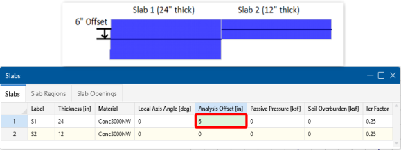
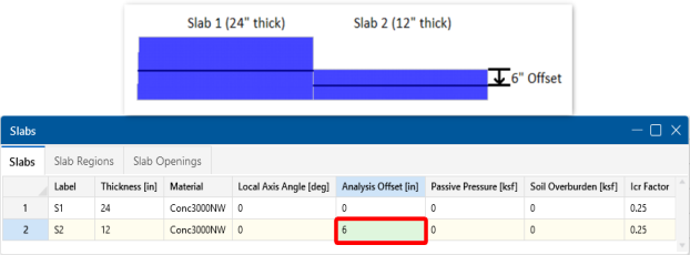
Analysis Offset
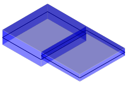
This is a positive value that will move the slab downward in relation to any other element in the model. This not just a graphics change. The program is internally adjusting the location of the slab and connecting it to surrounding elements with rigid links. You can expect to see different distribution of forces due to the offset.
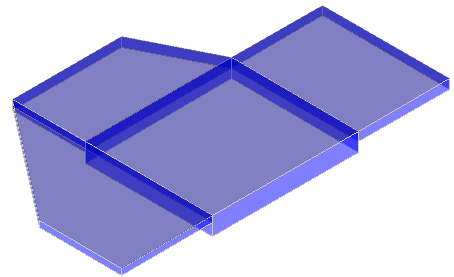
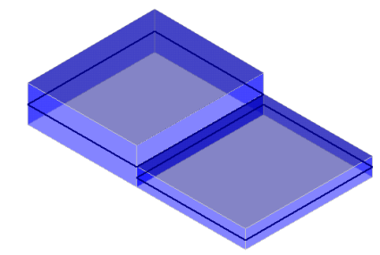
Example 1: This is an example of two slabs with no Analysis offset. The slabs are connected at their centerlines.

Click on image to enlarge it

Click on image to enlarge it
Example 2: This is an example of the slab offset in order to align the tops of each slab.
Click on image to enlarge it
Example 3: This is an example of the slab offset in order to align the bottom of each slab.
Click on image to enlarge it
Passive Pressure
The Passive Pressure represents a soil pressure used to calculate sliding resistance. The passive pressure is multiplied by the vertical area of the slab in the slab's local z and local x directions. This total force is added to the sliding resistance from friction in the Slab Stability Results Spreadsheet.
- The passive resistance only applies to sliding resistance and has no effect on overturning.
- The passive resistance applies to each individual slab and the presence of adjacent slabs has no effect.
- Thickened regions are not considered when computing the force from passive pressure.
Soil Overburden
The Soil Overburden represents a soil pressure on top of the slab which is also considered to calculate resistance to overturning and sliding. The soil overburden pressure is multiplied by the area of the slab and is scaled to reduce the magnitude for the areas of pedestals, stem walls, columns and post. This total force is added to the overturning resistance in the Slab Stability Results Spreadsheet.
Icr Factor (Cracked Moment of Inertia Factor)
The Icr Factor is used to reduce the bending stiffness of slabs. If this entry is left blank, the Icr factor will default to a value of 0.25.
Service Level Stiffness
Due to cracking and material non-linearity, modeling the stiffness of concrete members is more complex than it is for steel or wood members.
For typical applications, ACI 318-14 Section 6.6.3.1 (ACI 318-11 Section 10.10.4) requires that member stiffness be reduced to account for the cracking that occurs when a member is subjected to ultimate level loads. As described in the previous section, RISA uses the Icr Factor to account for this stiffness reduction. However, for service level analysis, the level of cracking will be significantly less. Therefore, the stiffness used in your analysis should be representative of the reduced loading and reduced cracking. Per ACI 318-14 Section R6.6.3.1.1 (ACI 318-11 Section R10.10.4.1), the program will account for this increased stiffness by applying a factor of 1.43 to the cracked section properties for any load combination that has the “Service” flag checked in the Load Combinations Spreadsheet.
Automatic Slab Meshing
RISAFoundation uses a Finite Element based approach to solving a Slab foundation model. As such, each slab will be automatically sub-meshed into a series of plate elements. This plate element mesh is very important for determining the quality of the structural model.
The Mesh Size, set on the Solution tab of the Model Settings, is the most important entry for controlling the size of your model. This is the starting size of plate element grid. This entry can be adjusted larger or smaller depending on the size of your slab. Generally speaking, a very large mat would need a larger mesh size, whereas a smaller mat would require a smaller mesh size.
Control Points
In addition to the mesh size, any points on the boundary of the slab and any support points within the slab will be considered control points. These control points are "fixed" points within the mesh and will dictate the layout of individual plates surrounding them. Any control points that are closer than the mesh distance specified in the Model Settings will cause an error message to occur during solution.
- Points which are used to apply loads are NOT automatically considered part of the plate mesh. These loads will be attributed to the surrounding nodes based on the local element stiffness and the location of the applied loading.
- Points which are not automatically meshed into the slab will have their soil pressure and deflection reported as a linearly interpolated value between the nearest meshed slab plate corner values.
Meshing Adjacent Slabs
When two slabs share a common border, each slab will initially be meshed individually. However, the mesh will then be modified so that all plate nodes line up at the slab borders. This is done to ensure perfect force transfer across the slab connection.
Modeling Complex Slabs
The automatic meshing routine can produce odd meshes for complex geometries. Therefore, it can be beneficial to model the slab as multiple adjacent slabs instead. This will force a more rectangular meshing pattern at borders between slabs. The image below shows what kind of an effect modeling an octagon foundation out of multiple slabs can have on the final plate mesh.
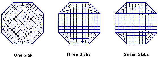
It should be stressed that ALL of the meshes shown above are good meshes that will produce accurate results. However, the image clearly shows how modeling adjacent slabs can force a more uniform and symmetric mesh.
Limitations
Foundation slabs do not consider any long term deflections effects from creep.