Building Sections
How it Works
The sections that you create will be made up of basic shapes. You may double-click or drag-and-drop these shapes from the shape library to the workspace where you build the overall section. Working on the optional drawing grid you may reposition and resize the basic shapes to achieve the desired cross section.
The properties of the section may be continuously updated as you edit and refine your section. Once you have completed the section you may build a report for printing or save the file for future use in RISASection or for importing by RISA-2D, RISA-3D, and RISAFloor.
Some Basic Terms and Notations
- A Shape is the basic component that can be used to create Sections. The properties of an individual Shape can be determined and its dimensions can be modified. New Shapes can be created and predefined Shapes from standard libraries can also be used and modified.
- A Shape Library is an area on the program interface where standard Shapes can be obtained.
- A Section is a combination or collection of Shapes placed together to act as a single cross-section.
- A Property Multiplier is used to specify the relative weight of the Shape in the over all Section. Generally, it is the ratio of the Modulus of Elasticity of a particular shape and the Base Modulus of Elasticity (you can adjust this in the Section Properties tab of the Options menu). However, any positive, negative or zero value may be specified.
Basic Steps
To Build and Solve a Section
- When you open the program, you are given a window that allows you to open an existing project, or, if you close the window, you can begin a project from scratch.
- If you begin a project from scratch, you are ready to begin building your section. Remember, RISASection allows you to build multiple sections within a single file name. To add a new section to an existing file click
 and click
  to rename the section.
- Select common shapes from the database of shapes in the Shape Library on the left side of the application. Double-click or drag-and-drop shapes from the libraries to the workspace.
- If using generic shapes (from the "Basic" libraries ) you may re-size the shapes in the Shape Editor once they are in the workspace by double-clicking the shape edge and entering the basic dimensions.
- Reposition the shapes using the stacking and aligning tools or click
 to use the Shape Layout Editor.
- Click
 and
and  to calculate the properties if they aren't updating automatically.
- Click
 to print the current section or click
  to build a report.
Notes:
- Alternatively you can import a shape from a DXF. Please see the DXF Import topic for more information on how to import these shapes.
- See the following sections to learn how to manipulate the shapes once you have added them to the section. It is important to give unique, descriptive names to each section so that you can discern them for use in RISA-2D, RISA-3D, and RISAFloor. Sections will be displayed by the Section name as well as the File name.
Selecting Shapes
After shapes have been added to the workspace from the library you may select one or more to move and edit in order to properly define the section.
Single Shapes
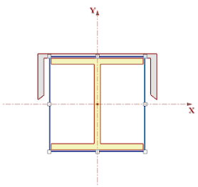
To select a single shape you may either click the edge of the shape or draw a box that contains only one entire shape (the box may contain part of another shape). The selected shape will be shown as above (outlined with a dashed line with sizing handles that may be used to stretch the shape).
Multiple Shapes
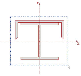
To select multiple shapes you may either hold down the shift key while clicking on the individual shapes, or draw a box that entirely contains the multiple shapes, as shown above. Shapes not entirely within the box will not be selected. The selected shapes will be shown outlined with a dashed line.
How to Use Shape Draw and Color Notation
All Shapes are drawn in true proportions on the screen as well as on the paper. The drawing area is automatically scaled to fit the Shapes. To create extra space around the Section or Shape drawing, you can use the zoom down button.
Closed Shapes are filled with appropriate color in the Rendered view. The open Shapes are drawn as single lines, irrespective of the actual thickness of the plate or sheet.
By default, different colors are used to draw and fill Shapes of different material or type. Separate colors are used for Concrete, Hot Rolled and Cold Formed Shapes. To change the colors used in drawing these Shapes, use the View tab in the Options menu. You can specify the border and fill colors for various types of Shapes. See View Options for more information.
Moving and Editing Shapes
There are a number of ways that you can edit the shapes after they are added from the Library to the Section. Some actions may be performed on multiple shapes simultaneously by first selecting the desired shapes. Snapping may also be used in conjunction with some of the methods to restrict stretching and moving to the nearest grid line. Grid snapping may be turned on and off by clicking  .
.
Dragging Shapes
Dragging may be performed on individual shapes or selected multiple shapes by clicking and dragging the edge of a shape.
Note: This may be easier if you turn off the Snap to Grid option. Simply click the Snap to Grid button  to toggle this option on and off.
Stretching Shapes
Stretching (resizing) a single shape may be done by clicking the shapes edge to display resizing handles and then clicking and dragging the handles.
Note: You cannot stretch pre-defined shapes from one of the Hot Rolled Shape Databases or any merged shapes.
Rotating Shapes
The graphic editing rotate buttons are provided on the RISA Toolbar:
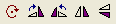
These buttons help you rotate and flip the selected shapes in the workspace.
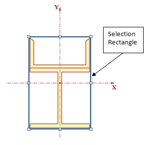
Note: Because you can rotate a single shape, or a group of shapes, the rotate is always in reference to the centroid of the selection rectangle, not necessarily the centroid of the selected shape.
Aligning and Stacking Shapes
The graphic editing rotate buttons are provided on the RISA Toolbar:
The Alignment buttons  help you align the sides or centers of selected shapes.
The Stacking buttons  help you stack selected shapes on top of one another or side-by-side.
The Parallel Alignment button  helps you align shapes per their parallel edges.
Merge and Explode
The general properties will automatically update to include all shapes in the section. However, you may want to merge the sections in order to get a more accurate Torsional J calculation. To do this, simply click the Merge button  . If you want to un-merge the shapes, simply click the Explode button
  .
.
Note:
- Only shapes of the same material will merge.
- Shapes with a Property Multiplier of -1 (designating a void) will not merge.
Cutting and Pasting Shapes
You may cut and paste single or multiple shapes by selecting the shapes and then clicking cut  , copy
  , or paste
  .
.
Shape Editor
The Shape Editor may b used to adjust the dimensions of a single shape.
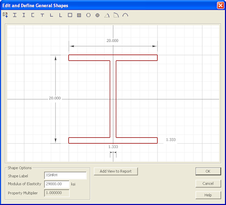
Double-click the edge of the shape or select the shape and click  to open the Shape Editor. This editor may be used to redefine the basic dimensions of the shape, shape label and modulus of elasticity.
The main part of the editor displays the shape and its dimensions. You can edit the dimensions by highlighting the values and specifying new dimensions. You can show the modified shape by pressing the Refresh button. You can also change the shape type by choosing from the toolbar on the top. The toolbar presents shapes from the same shape family such as Basic Concrete Shapes and Basic Steel Shapes.
You may also edit the Shape Label and Modulus of Elasticity. The Property Multiplier is a ratio between the input Modulus of Elasticity and the Modulus of Elasticity of Steel (29000 ksi).
Note
- You may not edit shapes in the RISA HR Databases. To specify custom shapes, choose the shape from the Basic Steel Shapes or Basic Concrete Shapes options in the Shape Library and edit the shape dimensions to define the custom size.
Shape Layout Editor
The Shape Layout Editor may be used to adjust the position of the individual shapes based on their centroid coordinates relative to the origin of the workspace.
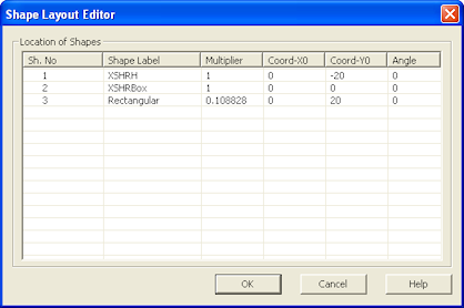
Click to open the Shape Layout Editor.The Shape Layout Editor lists all shapes currently in the section and lets you view and edit the Label, Multiplier and position of each shape. The editor is a spreadsheet with each shape listed on it's own line and the columns are as follows:
| Column Label |
Description |
| Sh. No |
Shape number (non-editable) |
| Shape Label |
Description of the basic shape |
| Multiplier |
Multiplier used for transformed section properties (1.0 implies the modulus of elasticity of steel) |
| Coord-X0 |
X-coordinate of the shape centroid |
| Coord-Y0 |
Y-coordinate of the shape centroid. |
| Angle |
Rotation of the shape in the counter-clockwise direction. |
Note: If your Section contains merged shapes, the Shape Layout Editor will by default only display the information pertaining to the overall (merged) Section. However, you can expand this to also show the properties of the individual merged shapes.

Solving for Properties
RISASection calculates most properties automatically as you edit the section. See the Property Calculations section for more information about what properties are calculated.
Saving Section Files
Sections are saved in files with a .nmsx extension by default. Multiple sections may be created and saved in one file, so you could have a file called STEEL.nmsx and one called CONCRETE.nmsx that store your steel and concrete shapes separately. You might name your files by project instead. That is completely up to you. All sections in a file are saved together by clicking  just once.
RISA-3D, RISAFloor, and RISA-2D look for all .nmsx files in the directory specified under Tools - Application Settings- File Locations tab and simultaneously provide a list of all sections that exist in any of the .nmsx files. You can see which sections are available by clicking on the shape database within RISA-3D, RISAFloor, or RISA-2D.Then click on the General tab or the Hot Rolled tab (depending on which Material you selected in RISASection). Under Database/Manufacturer you can select RISASection. You will then be able to see the sections available to you. The list provided is of the names of the sections within each section file, so it is important to use unique, descriptive names for each section you create.
See the Integration topic for more information.