These examples are designed to teach you about the features that are available so that you may then build any shape that you need. The process is similar for all sections you will use basic shapes from the library to describe each section. The shapes will be taken from the library and placed in the workspace. You will then rotate, align and stack the shapes to configure the section. This process will be repeated for each section that you want to describe in the file and then you will simply print a report and save the file.
Because each file can contain multiple sections, you will also learn how to rename sections and designate them with Material and Shape Type for import into RISA-2D, RISA-3D, or RISAFloor.
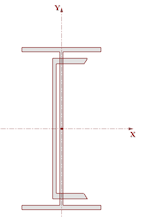
In this example we will define two steel sections in one file. The first will be a tapered wide flange, and the second will be a wide flange with a cap channel.
Note - You may click the Undo button at any time to correct mistakes.
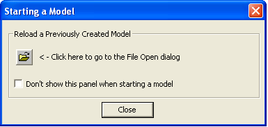
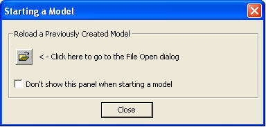
1. Start RISASection by clicking the shortcut on your desktop or selecting it from the Windows Start menu. RISASection will open a new file and present you with the Starting a Model dialog.
2. This dialog allows you to quickly access previous files. However, you will be starting a fresh model in this example, so click Close to close the dialog.
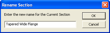
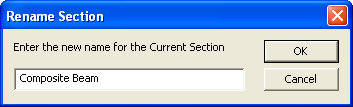
3. Click the Rename Section button
from the RISA Toolbar. Type in "Tapered Wide Flange" and click OK.
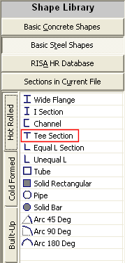
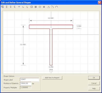
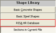
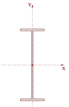
4. On the left side of the application, under Shape Library, click Basic Steel Shapes. Double-click the Tee Section shape it will be added to the workspace.
5. Edit the shape properties in the Shape Editor. To open the Shape Editor, double-click the edge of the shape that is now in the workspace.
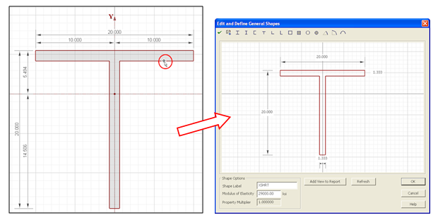
6. Change the flange width by clicking in the top dimension box and type "12". Repeat to change the flange thickness to 1", the depth to 11" and the web thickness to 0.75".Click OK to close the editor.
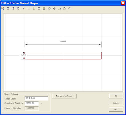
7. Next, double-click the Solid Rectangular shape from the Basic Steel Shapes Library to add it to your section.
8. Double click the edge of the Solid Rectangular shape to open the Shape Editor. Change the width to 8" and the depth to 0.75". Click OK to close the editor.
9. Next, you will move the shapes into the appropriate locations. In RISASection, you can always drag and drop sections manually, but for this example, you will use the Alignment and Stack tools to move the bottom flange.
Start by selecting both shapes: click on Select All from the Edit menu.
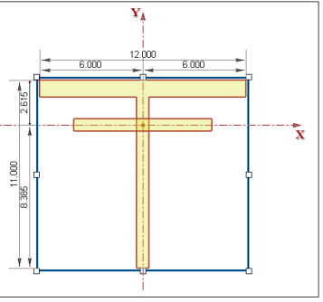
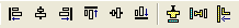
10. Click the Align Bottom button
first.
11. Next, click on the Stack Shapes Vertically button
.
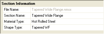
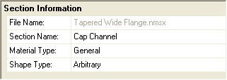
12. The next step is to assign the section the appropriate Material and Shape Types for integration with RISA-2D, RISA-3D, or RISAFloor.
In the Section Information window, select Hot Rolled Steel from the Material Type drop down menu. Then, select Tapered WF from the Shape Type menu.
13. Click the Merge button
to merge together the two shapes into a single shape. This will ensure that you get the most accurate Torsional J calculation.
14. Click the Solve button
and the Torsional J Solve button
to update the results.
15. Finally, save the file by selecting Save Section File from the File menu. Continue with the next example to learn how to add multiple sections to one file.
1. Continuing from the previous example, you will now add a new section to the existing file. Click the Add New Section button
from the RISA Toolbar. This will automatically open a new section with a blank workspace.
2. Under the Shape Library, click on RISA HR Database.
3. Make sure that the Database selection (on the Window toolbar) is set to AISC.
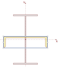
4. In the database on the left, double-click W14X30 in order to add it to your workspace. Since this is a shape taken directly from the program databases, the dimensions are all preset and so you do not need to modify anything.
5. Next, click on the Channel tab
and double-click on the C12X20.7 to add it to the section.
6. Click on the edge of the channel section to select it.
7. Click the Rotate Right button
to flip the channel 90 degrees.
8. Click CTRL + A on your keyboard to select all shapes.
9. Select the Align Center button
. Notice that this snaps the vertical axis of the wide flange to the centroid location of the channel. This is a bit off from the origin, so next, you will manually move these back.
10. Select Shape Layout from the Section menu. This will open the Shape Layout Editor.
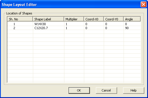
11. Make sure that the Coord-Y0 value of both Shape Number 1 (W14X30) and Shape Number 2 (C12x20.7) to 0. Click OK to close the dialog and make the changes.
12. Next, click on the channel, so just that one shape is selected. Click the Parallel Align button
on the Window Toolbar. Then, click on the inside edge of the channel web. Last, click on the upper edge of the top flange on the wide flange shape.
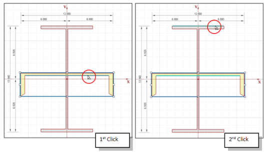
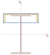
13. This will move the channel shape up so that it is now sitting on top of the wide flange.
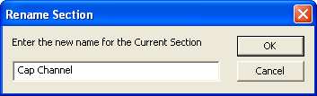
14. Finally, rename the section by clicking the Rename Current Section button
and then typing in “Cap Channel”.
Since this shape does not fall within one of the predefined Hot Rolled Steel Shape Types, leave it designated as a General Material, Arbitrary Shape.
These example explore building shapes with multiple materials.
Note - You may click the Undo button at any time to correct mistakes.
1. Start RISASection and open a new file.
2. Click Close to close the Starting a Model dialog.
3. Click the Rename Section button
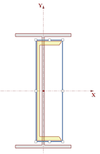
from the RISA Toolbar. Type in "Composite Beam" and click OK.
4. Under the Shape Library, click on RISA HR Database.

5. Make sure that the Database selection (on the Window toolbar) is set to AISC.

6. In the database on the left, double-click W36X150 in order to add it to your workspace. Since this is a shape taken directly from the program databases, the dimensions are all preset and so you do not need to modify anything.
7. Next, click on the Basic Concrete Shapes Library. Double-click on the Rectangular shape to add it to your section.
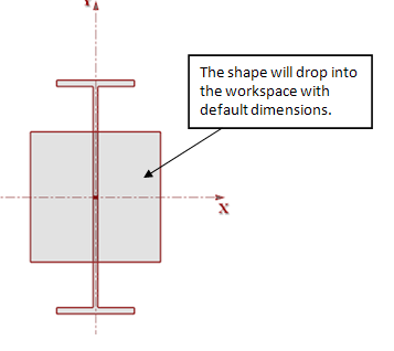
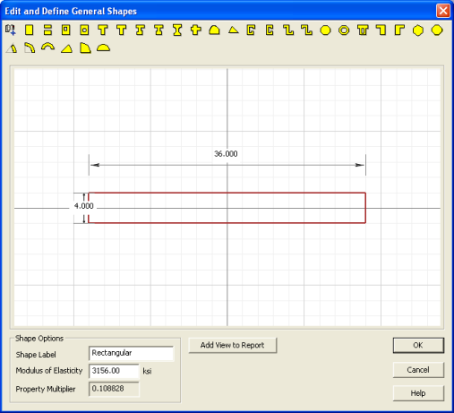
8. Double click the edge of the Rectangular shape to open the Shape Editor. Change the width to 36" and the depth to 4". Click OK to close the editor.
9. Next, you will move the shapes into the appropriate locations. In RISASection, you can always drag and drop sections manually or use the Alignment and Stack tools, but for this example you will manually adjust the centroid location in the Shape Layout Editor.
Select Shape Layout from the Section menu. This will open the Shape Layout Editor.
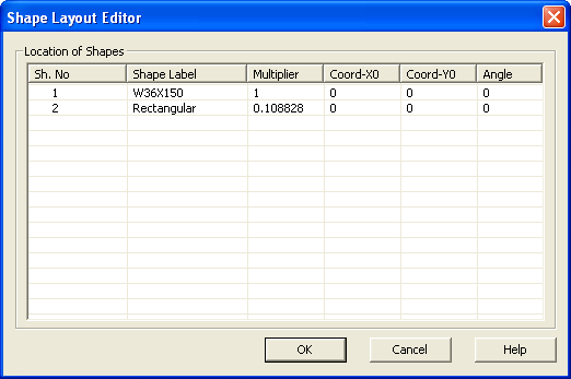
Notice that the Rectangular shape has a Multiplier of 0.108828. This is because you selected it from the Basic Concrete Shapes library. This means that the Rectangular shape has a Modulus of Elasticity equal to 0.108828 x 29000 ksi = 3156 ksi.
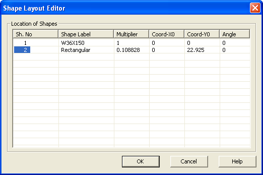
10. Change the Coord-Y0 value of Shape Number 2 (Rectangular) to 22.925. Click OK to close the dialog and make the changes.
11. Click the Reset View button
to see the full section.
12. Next, define the Material and Shape Type in the Section Information window.
Since this shape does not fall within one of the predefined Hot Rolled Steel Shape Types, leave it designated as a General Material, Arbitrary Shape.
13. Click the Solve button
and the Torsional J Solve button
14. Finally, save the file by selecting Save Section File from the File menu. Continue with the next example to add another section to the file.
1. Continuing from the previous example, you will now add a new section to the existing file. Click the Add New Section button
from the RISA Toolbar. This will automatically open a new section with a blank workspace.
2. Under the Shape Library, click on Basic Concrete Shapes.
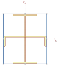
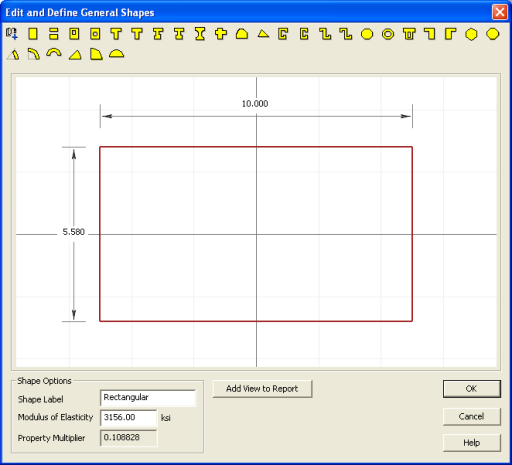
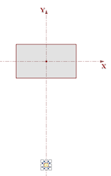
3. Double-click Rectangular to add it to your workspace.

4. Double click the edge of the Rectangular shape to open the Shape Editor. Change the width to 10" and the depth to 5.58". Click OK to close the editor.
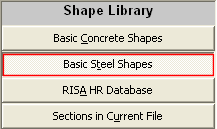
5. Next, click on the Basic Steel Shapes database under Shape Library.
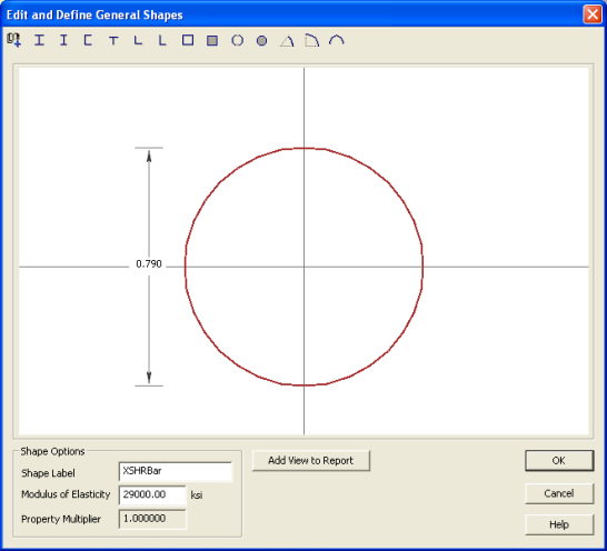
6. Double-click on the Solid Bar shape to add it to your section.
7. Double click the edge of the Solid Bar shape to open the Shape Editor. Change the diameter to 0.79". Click OK to close the editor.
8. Next, move the Solid Bar down to the correct location. Open the Shape Layout Editor
and change the Y0 coordinate of Shape No. 2 (XSHRBar) to -17.21.
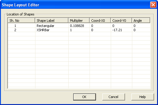
Click OK to close the editor.
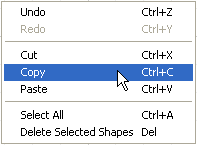
9. Next, you will copy the Solid Bar shape twice to add the remaining shapes. Select the Solid Bar shape by clicking on its edge.
10. Use the right-click menu to first Copy the selection and then Paste it twice.
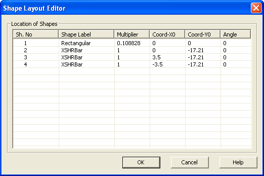
11. Reopen the Shape Layout Editor and change the coordinates of the two new bars to match the following:
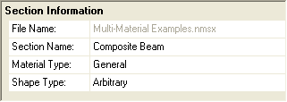
12. Finally, rename the section by typing “Cracked Section” into the Section Name entry in the Section Information window.
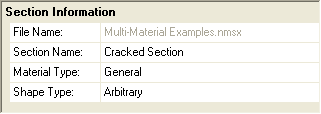
Since this shape does not fall within one of the predefined Hot Rolled Steel Shape Types, leave it designated as a General Material, Arbitrary Shape.
13. Save the file by clicking on the Save Section File button
.