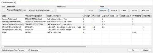
Add a new Load Combination. Make sure to select Cracked Deflection for the combination's Analysis/Design option. An example is highlighted below.
Click image to enlarge
Go to the Analysis>Analysis and click the Execute Analysis  icon.
icon.
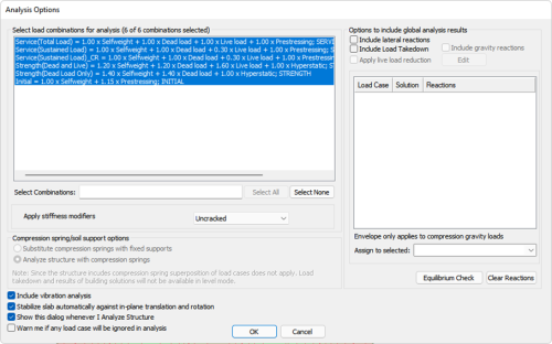
In the Analysis Option dialog, set the settings you wish to use and make sure to choose all load combinations being used for design including the Cracked Deflection combination(s) in the selection of combinations for analysis.
Click image to enlarge
Save the solution when prompted.

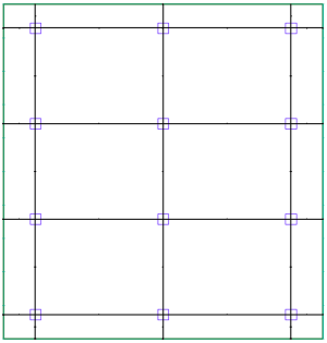
Add support lines to the model.
Click image to enlarge
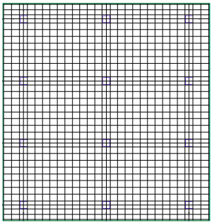
Generate the design sections along the support lines.
Click image to enlarge
Enter base reinforcement into the model that you want accounted for in the analysis if any is needed. (Any additional calculated reinforcement needed in the section based on strength or minimum code requirements will be included as well.)
Go to Floor Design>Section Design and click the Design the Sections  icon.
icon.
When prompted click YES to save the design solution.

Go to Floor Design>Rebar and click on the Calculated Rebar Plan  icon.
icon.
View the calculated reinforcement and modify as needed.
Go to Analysis> Analysis and click the Cracked Deflection  icon.
icon.
When the analysis finished click OK to save the results.
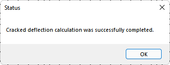
Once the results are saved you can View the Cracked Deflection Analysis Results.
