Click on image to enlarge.
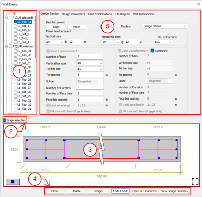
The Wall Design Manager image is broken into five parts as described below.
-
Wall Design Section List - The wall design section list at the left edge of the window identifies each pier and the top and bottom design sections of walls belonging to each pier. Nomenclature for the wall design section names is described in Section 10 of this document.
-
Single Selection – This checkbox, when selected, limits the user to select only 1 design section at a time. If the box is unchecked, multiple design sections can be selected at the same time. Reinforcement input items that don’t contain the same values when multiple sections are selected will show ellipses (…..) until the values of all selected sections are identical. If more than 1 design section is selected, the graphical design section window will not render an image and the warning shown below will appear.
-
Graphical Design Section Window – This window allows the user to view the selected design section with accompanying zone and panel reinforcement and dimensions. The window can be toggled to different modes as described below.
Click on image to enlarge.
-
 Reinforcement in the section is shown by bar representation for vertical and horizontal reinforcement and transverse wall ties. Overall wall dimensions and zone dimensions are shown.
 -
 The graphical image shown is a zoomed view showing detailed zone reinforcement while reducing the panel region. As shown above.
 -
 The graphical image shown is a full-scale view showing the entire design section. As shown below.
Click on image to enlarge.
-
Reinforcement in the section is shown by lump sum approach. The total area of steel and reinforcement ratio in zones and panel and reinforcement are displayed at their individual CGS locations.
Click on image to enlarge.
-
-
The buttons located at the bottom of the Wall Design Manager window are listed and describes below.
-
Close – Closes the ADAPT Wall Design Manager.
-
Update – Updates the selected design section/s to the values set in the reinforcement input fields after user modification after a section has been designed.
-
Design – Designs the selected design section/s. If reinforcement size and/or spacing is not adequate, the program will update the reinforcement fields necessary to meet the selected codes design requirements.
-
Code Check – Checks the selected design section/s reinforcement and spacing against design provisions for the selected design code.
-
Open in S-Concrete – If selected, the design section and data is opened in S-Concrete. An active license of S-Concrete is required for this option.
-
View Design Summary – Opens the HTML summary document for the selected design section/s after a code check or design has been performed.
-
-
Wall Design Manager Tabs; Design Section, Design Parameters, Load Combinations, PM Diagram, and Wall Intersection. Only the tabs that have differences from the main topic are described below.
Design Section
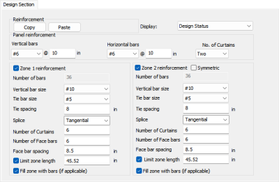
The Design Section tab allows you to define reinforcement for each section type in the Wall Design Section List. The Design Section tab is shown in the image below.
Click on image to enlarge.
The following table provides descriptions of the options available in the Wall Design Manager - Design Sections tab. Click on the +sign to expand the table. Click the + sign below to expand the table.
| Option | Description |
|---|---|
|
Reinforcement:
Click on image to enlarge. |
|
| Copy | Copies the reinforcement for the selected design section(s). |
| Paste | Pastes the copied reinforcement to the selected design section/s reinforcement assignments. |
|
Display: Click on image to enlarge. |
|
| Design Status | Shows status next to each design section name as “acceptable” or “unacceptable” after the section has been designed or code checked. The status is shown as green or red. |
| V&T Utilization | Shows the status of shear and torsion interaction as “acceptable” or “unacceptable” if the value is less than, equal to, or greater than 1.0. The status is shown in green or red. |
| N&M Utilization | Shows the status of axial force and flexure interaction as “acceptable” or “unacceptable” if the value is less than, equal to, or greater than 1.0. The status is shown in green or red. |
|
Panel Reinforcement: Click on image to enlarge. |
|
|
Vertical bars |
Defines the bar size and spacing of vertical reinforcement (parallel to the vertical wall axis) in the wall panel (that portion of the wall between zones.) |
|
Horizontal bars |
Defines the bar size and spacing of horizontal reinforcement (perpendicular to the vertical wall axis) in the wall panel. |
|
No. of Curtains |
The number of vertical bar layers in the wall local s-s axis direction. |
|
Zone Reinforcement Click on image to enlarge. |
|
|
Check box for Zone 1 and Zone 2 |
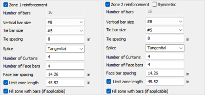
If the checkboxes are active and selected, the program considers boundary zone design. If de-selected the program considers only the zone that is selected. Deselecting both means the wall is designed as “zone-less.” |
|
Check box for Symmetric |
If zones are considered for design and symmetric is selected, Zone 2 becomes disabled and takes on the same reinforcement as defined for Zone 1. |
|
Number of bars |
Not active. Total number of vertical bars is defined by the face bars and curtain assignment for the zone. |
|
Vertical bar size |
Defines the bars size for vertical bars. |
|
Tie bar size |
Defines the tie (transverse containment) bar size. |
|
Tie spacing |
Defines the spacing of the tie bars. |
|
Splice |
Active only when checking spacing of vertical bars in zones. Tangential, bearing, radial or mechanical can be defined. See S-Concrete documentation for definitions of each. |
|
Number of Curtains |
Defines the number of vertical bar layers in the wall local s-s axis direction. |
|
Number of Face bars |
Defines the number of vertical bar layers in the wall local r-r axis direction. |
|
Face bar spacing |
Defines the spacing of face bars. The spacing is in the local r-r direction. |
|
Limit zone length |
Design parameter that limits the length of the boundary zone. |
|
Fill zone with bars (if applicable) |
This option forces reinforcement to be placed at every possible location where a curtain and face bar location intersect from the outer zone edge to the inner zone edge when selected. |
Design Parameters
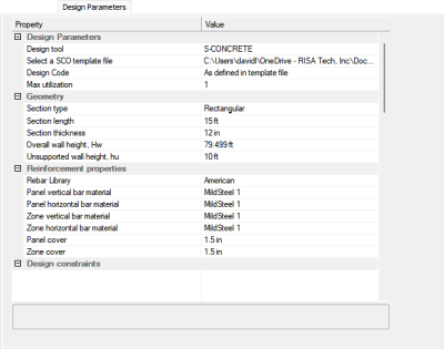
The Design Parameters tab offers different options when S-Concrete is chosen as the design engine. The Design Section tab when S-Concrete is the design engine is shown in the image below.
S-Concrete:
Click on image to enlarge.
The following table provides descriptions of the options available in the Wall Design Manager - Design Parameters tab..Click the + sign below to expand the table.
| Option | Description |
|---|---|
|
Design Parameters:
|
|
| Design tool | S-Concrete |
|
Select a SCO template file |
When S-Concrete is selected as the design tool, this additional input parameter is required. A .SCO file needs to be saved from S-Concrete in order to define additional design parameters not assigned in ADAPT-Builder. Those parameters and properties defined in ADAPT-Builder which are shared with S-Concrete are mapped to S-Concrete when the application is run for design or code check OR when the application is launched independently. The additional design parameters are taken from the defined .SCO file. For example, the .SCO file contains parameters assigned the Section assignments. Parameters included in this input that are not defined in ADAPTBuilder are Seismic Parameters, Slenderness Effects, Effective Section Properties and Design Constraints. |
| Design code | Design code used is that set in the .SCO file. |
| Max Utilization | Sets the maximum demand/capacity interaction ratio for V&T and N&M. |
| Geometry:
|
|
| Section type | Rectangular or I-Section. The design section graphical view changes according to what is being represented. |
| Section length | Design section length. Taken as the length of the wall that the design section is assigned to. |
| Section thickness | Design section thickness. Value is the panel thickness. |
| Overall wall height, Hw | This is the total height of the wall stack. This is calculated by the program and can be overwritten. |
| Unsupported wall height, hu | This is defined as the wall segment height between slabs. The default is 3ft (3m). The user must override value to correct unsupported wall height. |
|
Reinforcement Properties:
|
|
|
Sets the rebar library defined in Criteria>Preferred Reinforcement Size and Material. Value can be American, SI or MKS. |
|
|
Panel vertical bar material |
Sets the panel vertical reinforcement material assignment as defined in the Material pull-down menu. |
|
Panel horizontal bar material |
Sets the panel horizontal reinforcement material assignment as defined in the Material pull-down menu. |
|
Zone vertical bar material |
Sets the zone vertical reinforcement material assignment as defined in the Material pull-down menu. |
|
Zone horizontal bar material |
Sets the zone horizontal (ties) reinforcement material assignment as defined in the Material pull-down menu. |
|
Panel Cover |
Sets the panel reinforcement cover dimension. |
|
Zone Cover |
Sets the Zone Cover dimension. |
|
Design Constraints: Design constraints are defined in the .SCO file.
|
|
P-M Diagram
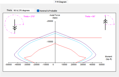
The program will produce axial-flexure interaction diagrams for the code checked or designed section. The available list of theta angles is comprehensive with multiple options. The Design Section tab is shown in the image below.
Click on image to enlarge.
The option for Nominal & Probable includes additional graphs representing these additional diagrams.
See the Wall Design Manager topic for additional information.




 icon.
icon.