The plate/shell finite element allows you to easily model shear walls, diaphragms, shells, tanks and many other surface structures. Plate data may be viewed and edited in three ways: graphically, in the Information dialog or in the Plates spreadsheet. Loads must be applied as joint loads to the joints that define the plates. Loads may also be applied to adjacent beam members. (This would let you apply a distributed load along one edge of a wall, for example.)
There are several graphic-editing features that make the creation and modification of models quite easy. Use the Insert and Modify menus or the Drawing Toolbar to use these features in the model view. To create new members or plates, you can draw them using a drawing grid or draw "dot to dot" from existing joints. Once you have created these items you may use other graphic features to load the model and set boundary conditions.
Creating plate models requires more forethought than beam models. See Plate Modeling Tips and Plate Modeling Examples for tips on building plate models. To create new plates you can draw them using a drawing grid or draw "dot to dot" from existing joints. You can set all of the plate properties up front or you can modify these properties after you draw them. Modifying properties is discussed in the next sections. See Plate Spreadsheet for information on plates and their properties.
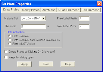
The Draw Plates tool lets you graphically draw plates in your model. Enter the appropriate plate parameters, click OK and draw plates between existing joints or on the drawing grid. You will also notice that the coordinates of the joint or grid point that is closest to your cursor are displayed in the lower right hand corner of the model view. The new plates will be shown on screen and will be recorded in the Plates Spreadsheet.
To actually draw a plate, you have two options. The fastest way is to use the Create Plates by Clicking on Grid Areas option, and then create plates by clicking on the grid areas formed by the intersecting grid lines. As you click on an area, a plate will automatically be created in that area. The second option is to create plates by drawing them one joint at a time. You click on the grid point or joint that you want to be the "A" joint for the plate, then you click on the "B" joint, "C" joint, and then the "D" joint in either clockwise or counter clockwise order. The plate will "stretch" like a rubber band as you draw from joint to joint.
The parameters shown are the same parameters that you would enter on the Plates Spreadsheet.
Note
There are a number of ways to modify plates. You may view and edit the member data in the Plates Spreadsheet. You may double-click a plate to view and edit its properties. You can use the Modify Members tool to graphically modify a possibly large selection of members.
The graphical Plate Modify tool discussed here lets you modify the properties of plates that already exist in your model. To use this, you will typically specify the properties you want to change, then select the plates that you want to modify. You can modify plates one at a time by selecting the Click to Apply option and then click on the plates you wish to modify. You may also modify entire selections of plates by selecting the plates first and then use the Apply to Selected option. See the Graphic Selection topic for more on selecting.
The parameters shown are the same as those used to define new plates.
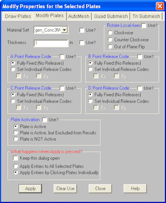
The Use? check boxes next to the data fields indicate whether the particular parameter will be used or not when the modification is applied. If the box next to a field is checked, that parameter will be applied to any selected plates. If the box is NOT checked, the parameter will NOT be applied, even if a value is entered in the field. This lets you easily change one or two properties on members without affecting all the rest of the properties. Note that if a no value is entered in a field (I.e. the field is blank) and the corresponding check box is checked, clicking “Apply” will have the effect of clearing the data for these fields.
These options allow the user to perform a clockwise, or counter clockwise rotation so that they can better align the plate local axes. It also allows the user to flip the local z-axis so that it is headed in the other direction.
Note
The AutoMesh tool allows you to draw a polygon that RISA-2D will automatically submesh into smaller quadrilateral plate elements. Just as with Drawing Plates, the material set and plate thickness of the plates within the mesh may be indicated prior to drawing the polygon. In addition to these parameters, a plate edge minimum can also be provided. Polygons of virtually any size and shape may be drawn provided the drawing lines do not cross. The polygon points must be on the same plane, either one of the three global planes (XY, XZ, or YZ) or co-planar. Polygons may be drawn in either a clockwise or counter-clockwise direction. To complete a polygon, simply double click on the last joint/grid intersection, or click on the starting joint/grid intersection. Once a polygon is drawn, RISA-2Dwill create a submesh of quadrilateral plate elements, limited by the edges of the polygon, and of a size corresponding to the plate edge minimum indicated by the user. Note that only quadrilateral plate elements are created with the AutoMesh tool.
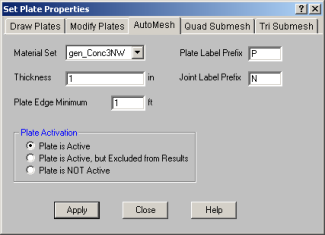
When drawing a polygon with the AutoMesh tool, any existing joints within the boundary and in the plane of the polygon will be considered control points. These Control Points will be considered "fixed" points within the mesh and will dictate the layout of individual plates surrounding them. It is important to note that only currently selected joints at the time the polygon is drawn will be used as control points.
The AutoMesh tool will attempt to use the Plate Edge Minimum that the user enters. However, if it cannot successfully create a valid mesh, it will automatically re-set the Plate Edge Minimum entry to an edge minimum equal to the minimum distance between two control points.
To AutoMesh a Polygon
Note
For additional advice on this topic, please see the RISA Tips & Tricks webpage at risa.com/post/support. Type in Search keywords: Plate Mesh.
You can submesh quadrilateral (4 sided) plate elements into a mesh of smaller elements. This new mesh can be any size up to the program limits for joints and/or plates. This is very useful for refining a coarse mesh of elements, just make sure that all adjacent plate elements (elements sharing an edge) maintain connectivity.
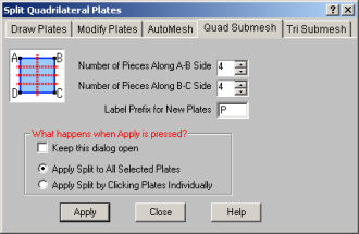
You can define different submesh increments in each direction. The A,B,C and D joints for each plate are displayed in the plates spreadsheet. The A joint is the first joint clicked on when you created the plate. The B joint is the second and so on. In addition, if the plate local axes is set to Nodal, you can determine which side is which by displaying the plate local axes and realizing that the local x-axis is parallel to the D-C edge of the plate.
You can submesh the plates one at a time by selecting the Click to Apply option and then clicking on the plates you wish to submesh. You may also modify entire selections of plates by selecting the plates and then using the Apply to Selected option.
To Submesh Quadrilateral Plates
Note
This is used to sub-mesh the selected triangular (3 sided) elements into a mesh of 3 quadrilaterals. This is done by first creating a new joint at the center of each selected triangular element and also at the center point along each edge of the triangular element. These new joints are then used to create three quadrilateral elements that replace the triangular element.
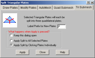
To Submesh Triangular Plates
Note
The Plates Spreadsheet records the properties for the plate/shell elements of the model and may be accessed by selecting Plates on the Spreadsheets menu.
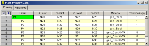
The following data columns hold the Primary data for the plates:
You may assign a unique label to any or all of the plates. You can then refer to the plate by its label. Each label has to be unique, so if you try to enter the same label more than once you will get an error message. You may relabel plates at any time with the Relabel Plates option on the Tools menu.
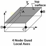
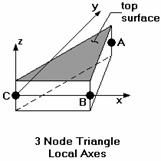
The A, B, C, and D joint entries are used to define the 4 corner joints of a quadrilateral element. (To define a 3-joint triangle element, just leave the D joint entry blank, or make it the same as the C joint.) The joints must all lie on the same plane and be entered in either a clockwise or counter-clockwise sequence.
The direction and sequence in which you define the joints determines how the elements local coordinate system is set up. This is discussed in the section on Plate Local Axes.
The material set label links the plate with the desired material defined on the Materials Spreadsheet.
Note
The thickness field on the Plates spreadsheet is the thickness of the element. This thickness is constant over the entire element.
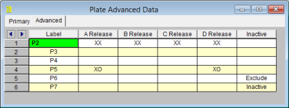
The following data columns hold the Advanced data for the plates:
The Plate Corner Releases for joints A, B, C, and D of each plate may be set in these four data columns. See Plate Corner Releases for more information.
The Inactive data column allows for plates to be set to 'Active', 'Inactive', or 'Excluded'. These choices may be made by selecting them from the drop down list or by entering an 'I' for 'Inactive' or an 'E' for 'Excluded'. If the cell is left blank the plate will be 'Active' by default. See Inactive and Excluded Plates for more information.
Just as with the joints and members you may double-click any plate to view it’s properties. All of the same information that is stored in the Plates Spreadsheet is displayed for the plate you choose, and may be edited. This is a quick way to view and change plate properties. For large selections of plates however the spreadsheet and graphic editing tools may be the faster solution.
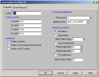
Label - You can view and edit the plate label.
Corner Joints - The corner joint labels are displayed for you to view or edit.
Thickness Material - The plate thickness (in the current dimension units) and the material may be viewed or edited.
Activation - The activation state of the plate may be changed. If the plate is made inactive, you will need to activate the plate from the Plates spreadsheet, or by using the Criteria Select feature to find and select inactive plates.
Meshing Options - The section allows you to mesh the current plate. You may choose between the auto-mesh function or the quad and tri submesh. Refer to the section on Modifying plates for information on meshing.
Note
The A, B, C, & D Release fields are used to designate
whether the forces and moments at the corners of the plate are considered
fixed to or released from the plates's points of attachment (the A, B, C, and D joints). Each plate has
To specify plate corner releases go to the A, B, C, or D Release
fields for the plate on the Advanced Tab of the Plates Spreadsheet, click the ![]() button,
and specify the condition.
button,
and specify the condition.
Alternatively, you may specify the corner condition by directly typing in the field. To indicate that a force component is released, put a 'X' for that component in the release field. You can move within the release field using the space bar which will result in a 'O' for no release.
Note
Making an item such as a member or plate inactive allows you to analyze the structure without the item, without having to delete the information that defines it. This leaves data intact so the item may be easily reactivated. This is handy if you want to try a model with and then without certain items, without having to actually delete the data.
Putting a "y" in the Inactive field makes the item inactive, i.e. the item is not included when the model is solved or plotted.
Another option is to put an "E". The "E" code means include the item in the solution, but exclude it from the results list. So, an item with an "E" in the "Inactive?" field will be treated like any other plate in the solution and plotting of the model, but the plate will not be listed in the solution results (forces, stresses etc.). This is useful if there are certain items whose results you're not interested in. You don't have to clutter up the results with these items and can concentrate on the items you're most interested in. See Printing for more limiting printed results.
The A, B, C, and D joints are used to define the corners of a quadrilateral element. (To define a 3-joint element, just leave the D joint blank, or make it the same as the C joint.) The joints must all lie on the same plane and be entered in either a clockwise or counter-clockwise direction.
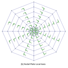
The direction and sequence in which you define the joints determines how the elements local coordinate system is set up. The plate local axes can be set to Global or Nodal in the Solution settings in the Model Settings. The following images depict the difference between Global and Nodal plate local axes, which are shown graphically in green. To view the plate local axes in such a manner, add the Plate Local Axes button from the available toolbar buttons. For more information, see Customizable Model View Toolbar.
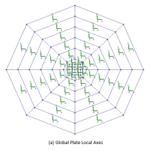
When the plate local axis is set to Global, the local axes of all plates will be oriented in the same orthogonal direction, regardless of plate geometry. However, the positive out-of-plane z-axis will be dependent on the configuration in which the plate or mesh was drawn. The plate local out-of-plane axis will always be the z-axis, but the positive direction of this axis will be dependent on the direction in which you define the joints of the plate. Defining the joints in a clockwise pattern will result in the out-of-plane z-axis pointing in the positive direction according to the global axes. For example, in the global XZ-plane, a plate drawn in the positive clockwise direction will result in the plate local out-of-plane z-axis pointing along the global positive Y-axis. Similarly, a counter-clockwise pattern will result in the out-of-plane z-axis pointing in the negative global axes direction. Plates do not follow the right-hand rule that is common in three-dimensional vector orientation. For more information on the interpretation of plate results based on local axis orientation, see Plate Force Results.
When the plate local axis is set to Nodal, the local x-axis is defined as positive from the D joint towards the C joint for 4 joint elements and from C towards B for 3 joint elements. The local y-axis is then placed as close to pointing towards the A-joint as possible. Note that for triangular elements, the y-axis will probably not pass through the A-joint. For 3 joint elements, the y-axis is “towards” the A-joint and perpendicular to the x-axis. Once the x and y axes are defined, the positive local z-axis is found using the right hand rule.
The following diagrams illustrate how the elements local coordinate system is related to the joint numbering sequence and direction:
The default plate local axis is set to Global. To change this to Nodal, see Solution settings in the Model Settings.
The element used is a mixed interpolation 4 joint quadrilateral element. By mixed interpolation, we mean that the in-plane and transverse shear strain components are derived independently. This allows the element to be easily simplified into a plane stress element in cases where transverse shear and bending are not desired. A reference for this element is Finite Element Procedures, by K.J. Bathe, Prentice-Hall, 1996. The book also provides many references for papers on the elements convergence and other characteristics. In brief, the element can model isotropic behavior for plane stress, plate bending and out-of-plane transverse shear.
This is accomplished by starting with the Mindlin-Reissner plate assumptions and adding interpolating functions for the out- of-plane transverse shear. This approach is analogous to incorporating shear deformation with flexural effects in beam theory. This results in an element that can be used for thin and thick plate applications. Traditional plate elements do not model out-of-plane transverse shear well (if at all) and cannot be used for thick plate applications. The element is also very insensitive to distortion.
Note:
RISA-2D also provides a 3-joint triangle element that can be used to build transitional meshes. The stress characteristics of the triangle are not as accurate as the 4-joint quad and use of the triangle should be limited. It is not recommended that the stresses from the 3-joint triangle be used at all. In fact, RISA-2D's AutoMesh tool will only create quadrilateral plate elements for this very reason. RISA-2D provides a way to convert your triangular plates to quadrilaterals, see Submeshing Triangular Plates.
The RISA plate element allows a limited degree of Orthotropic material behavior. Specifically, the In-Plane shearing of the plate will be almost entirely controlled by the G value for the material whereas the direct In-Plane compressive stiffness will be controlled by the Evalue of the material.
A word of caution is in order if you are new to plate modeling. Unlike modeling with beam elements, plate elements require some understanding of finite element behavior to successfully obtain meaningful results. It is easy to build a finite element model using the powerful generators and graphic editing tools. However, without understanding the limitations of the analysis method used, you can end up with an impressive looking but very inaccurate model. Even if you’ve been engaged in structural engineering for years, modeling with plates is not something most engineers do frequently. It is therefore not realistic to have the expectation that you should be able to perform complicated analysis with plate elements in a short amount of time. Good plate modeling takes time, knowledge of plate and finite element behavior, and experience.
The first tip is to read all the Plate documentation before embarking on an ambitious modeling project. This will save you much aggravation down the road.
The finite elements in a model should be as undistorted as possible. See the following figure:
A fast way to build a new mesh of finite elements is with the generation features. RISA-2D currently provides several generation features to quickly build common structures providing an easy way to create cylinders, cones, grids, radial grids and disks of plates. The best way to see what these features do is to experiment with them. See Generation to learn more about generation.
Another time-saving method is to draw large elements to represent continuums such as slabs and shear walls and then use the submesh features mentioned below to refine the mesh.
Note:
What if you’ve already built a model and you now decide that your finite element mesh is too coarse? To submesh elements see Submeshing Plates. Performing a Model Merge afterwards will insure that all the new elements get connected to existing beam elements and that duplicate joints get merged. See Model Merge for more information.
The program cannot provide a solution for plates which are poorly shaped or not planar. If any such "degenerate" plates exist, an error is produced during the solution. Use the Degenerate Plate Check utility in the Tools menu to fix these issues.
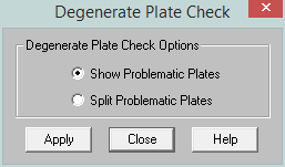
This utility can be used for two purposes:
While this will not be a comprehensive treatment of plate and finite element fundamentals, a review of certain key basic concepts and terminology will be valuable to the engineer who has not worked with finite elements, or has not had the opportunity to use them recently.
A place to start is with the types of forces or stresses that can occur in a plate. One term that is commonly used is “plane stress”. This term is used to describe a state of stress in a plate where all the stresses occur in the plane of the plate. A real world example would be a shear wall with forces applied only in the plane of the wall. The resulting plate forces would be just the normal stresses (Fx, Fy) and the in-plane shear stresses (Fxy). There would be no plate moments or out-of-plane shears generated.
It should be pointed out that the results for a plate are always a stress. These stresses are multiplied by the plate thickness and the width or length to obtain a force. Note that this force obtained is just an average value for the plate, since the stress was for a point on the plate and it undoubtedly will vary throughout the plate area. The fact that the stresses vary within a plate is why a good finite element mesh is so critical to obtain accurate results. Stresses tend to vary more around point loads and supports, and less in regions that are far from supports and have a uniform load.
A different example of plate forces would be a horizontal diaphragm that is loaded only in the out-of-plane direction. The plate results would be plate moments, out-of-plane shears, but no membrane (plane stress) stresses. The reason for no membrane stresses is that there was no in-plane loading.
One other comment on plate results is to point out the convention used for moments in plates. With beams, the My moment describes the moment about the local y-axis. However, with a plate element, the My moment is the moment that produces stresses in the local y-direction. The My moment in a plate is actually about the local x-axis. For more information, see Plate Force Results.
In a nutshell, finite elements tend to work by trying to approximate the correct deflected shape of the real world item being modeled. For example, if we are trying to model a horizontal diaphragm, simply supported on all edges, and loaded out-of- plane, our finite element model must able to approximately recreate the deflected shape of the diaphragm.
In order to do this with some accuracy, we must use a mesh of elements to represent the physical diaphragm. If we try to model the diaphragm with only one element (which is what everyone tries to do at least once), we will get very inaccurate results because one finite element cannot accurately model the deflected shape of the physical diaphragm. The multiple reasons for this are beyond the scope of this file, and if you want to understand the “why” please study a reference on finite element analysis such as Bathe’s book.
The most important concept to understand is that finite elements require a certain number of free or unrestrained joints in order to produce accurate results. Using enough elements in your mesh will produce accurate results for the deflection and stresses in the structural item being modeled. The gage of “enough” for common structural elements is addressed in the Plate Model Examples section of the Reference Manual.
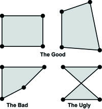
Finite elements are also affected by geometric distortion. The best shape for the 4-joint quadrilateral is a square. In practice, elements are frequently distorted, which is fine as long as they aren’t squashed too far out of shape. The largest internal angle should never be equal to or greater than 180 degrees, and preferably shouldn’t even approach 180 degrees.
One last item is that the element used by RISA-2D, like other plate/shell elements, cannot accurately model in-plane rotations. I.e., a plate/shell element will not provide resistance to a moment applied about the plate’s local z-axis. For example, let’s say you have a 4x4 grid of elements, simply supported about the edges, and you apply a joint moment to one of the internal joints so that the moment is about the local z-axis of the elements. RISA-2D will solve such a model, however you will get all zeros for the joint reactions and the element stresses. See Applying In-Plane Moments to Plates to learn how to work around this limitation.