Semi-Rigid Diaphragms
A semi-rigid diaphragm is one which distributes loads based on both the stiffness of elements which connect to it and on the stiffness of the diaphragm itself. For more details about semi-rigid diaphragms when RISA-3D is integrated with RISAFloor, see Semi-Rigid Diaphragms (RISAFloorES).
Semi-Rigid Modeling Tips for Concrete Floor Slabs
Lateral Elements: When modeling with a Semi-Rigid diaphragm, it's important to make all columns and walls Lateral. This will bring all the columns and walls into RISA-3D which will support the slab as the vertical loads are applied. In RISA-3D, the program will apply both lateral and vertical loads to the diaphragm for analysis of the lateral system. This is different than Rigid diaphragms because only the lateral resisting system needs to be transferred into RISA-3D.
Reinforcement Design: RISA-3D will not design the reinforcement for the slab. The reinforcement is designed in RISAFloor and is based on the vertical loads. However, you can find forces in the slab in RISA-3D using the tools listed below.
- Contours: The contours will display the global axis forces over the slab. See the Results View Settings - Diaphragms section of the RISAFloor help, for further information on display of the contours. The contours can be used to find the high and low forces as needed for reinforcement design.
- Internal Force Summation Tool (IFST): There is an IFST Slab tool that allows you to find forces from a point on the submesh to another point on the slab. This tool can be used to "cut" across the slab and will finds forces along the "cut". This is the same tool that is used internally in RISAFloor to find Auto-Design Cuts inside the Design Strips. For further information on this tool, see IFST for more details.
Semi-Rigid Modeling Tips for Beam Supported Floors
Lateral Elements: When modeling with a Semi-Rigid diaphragm, it's important to make all columns and walls Lateral. This will bring all the columns and walls into RISA-3D which will support the slab as the vertical loads are applied. In RISA-3D, the program will apply both lateral and vertical loads to the diaphragm for analysis of the lateral system. This is different than Rigid diaphragms because only the lateral resisting system needs to be transferred into RISA-3D.
Vertical Loads: The semi-rigid diaphragm has self weight and out-of-plane stiffness. Internally, the plates are modeled as normal so that there is stiffness out-of-plane. The diaphragm is used for out-of-plane and in-plane load distribution.
Diaphragm Material:The Semi-Rigid diaphragm material uses the General Materials. There are a list of default General Materials, however you can add to this list to match your diaphragm. See Materials for further information on creating your own General Material.
Diaphragm Thickness:The Semi-Rigid diaphragm thickness should be selected based on the approximate stiffness you expect from the slab or deck for lateral loading. The semi-rigid diaphragm is modeled using isotropic plates. Therefore, there is no association with the deck direction for the semi-rigid diaphragms. If your diaphragm is truly one-way, you may consider using a Flexible diaphragm.
Semi-Rigid Diaphragms for RISA-3D Only Models
RISA-3D does not have the ability to automatically define a Semi-Rigid diaphragm. However, Semi-Rigid diaphragms can be represented in the model using plates.
A semi-rigid diaphragm is modeled with plates, and requires you to model and submesh the plates appropriately. In order to adequately mesh your plates it is good to be familiar with Plate-Member Interaction. Plates are modeled using general materials, so the first step is to set up a material with the material properties of your diaphragm.
Click on image to enlarge it
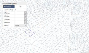
Next, model your plates using the specified material, and with an accurate thickness. Be sure to check the “Plane Stress” option. This makes it so that the plates only have stiffness within their own plane, and as a result won’t add any composite bending strength to the beams in the plane of the diaphragm.
Click on image to enlarge it
Semi-Rigid Diaphragms in a RISAFloorES Model
The Semi-Rigid diaphragm in RISA-3D helps you distribute the lateral forces based on the stiffness of the slab. When RISA-3D is integrated with RISAFloor, the program can create a Semi-Rigid diaphragm automatically. The Semi-Rigid diaphragm is defined in Diaphragm Parameters in a Beam Supported Floor and the Slab Definitions spreadsheet in a Concrete Floor Slab in RISAFloor.
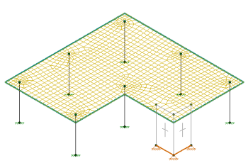
During the integration between RISAFloor and RISA-3D, the program creates a mesh of FEA plate elements within the edges of the slab. The thickness of the plates is defined by the slab/diaphragm defined in RISAFloor. The plate elements are automatically submeshed so that they attach to all vertical elements (columns and walls) as well as any new members or loads added into the RISA-3D model. Below shows an example of a simple L-shaped building with the mesh displayed.
Click on image to enlarge it
When the model is in RISA-3D, the mesh size is controlled by the Model Settings - Solution Tab -Semi-Rigid Mesh . For RISAFloor ES models, the slab stiffness can be reduced, based on the Icr factor in the RISAFloor Slabs spreadsheet and the Use Cracked Slabs checkbox in the Model Settings window in RISA-3D. The Icr slab stiffness only affects the out-of-plane stiffness. For further information on cracked slabs, see Elevated Slabs - Analysis in RISAFloor. The top of the columns are fixed to the diaphragm using links to distribute the forces over a 12"x12" area rather than a single column node. For further information see the Column Meshing section of the help in RISAFloor.


