Semi-Rigid Diaphragms (RISAFloorES)
The slab meshing is treated similar to analysis results. When the results of an analysis are deleted, the slab mesh is cleared to be re-built during the next solution. When a solution results file is saved, the meshed elements will be included in that file.
- This topic is only applicable for RISAFloor ES/RISA-3D combined models that have semi-rigid diaphragms. For information on semi-rigid considerations for RISA-3D only models see the Diaphragms topic.
- The program uses the finite element analysis, along with cracking factors (columns, beams and slabs) to come up with the stiffness of each element and the system as a whole. ACI 318-14 Sections 8.11.3, 8.11.4 and 8.11.5 (ACI 318-11 Sections 13.7.3, 13.7.4 and 13.7.5) provide ways to estimate the stiffness of individual elements in the equivalent frame method. These provisions are not used in the program.
RISA-3D Linked With RISAFloor

Click on image to enlarge it
The following table lists the General tab settings and their descriptions.
General tab settings
| Setting | Description |
|---|---|
|
Elevation |
Displays the elevation of the diaphragm. This is the same elevation as the floor which the diaphragm was created on. |
|
Mass |
Displays the dynamic mass tributary to the diaphragm. This mass is used to calculate seismic forces for both static and response spectra methods. |
|
Mass MOI |
Displays the dynamic mass moment of inertia of the diaphragm. This moment of inertia is used to calculate seismic forces for response spectra analysis. |
|
Center of Mass |
Displays the X and Z coordinates of the center of mass of each diaphragm. This is the location at which static (equivalent lateral force) seismic loads are applied for each diaphragm. |
|
Eccentricities |
Indicates the percent of length/width of the diaphragm, which are used to place "accidental eccentric" seismic loads for each diaphragm. This only applies to the static (equivalent lateral force) procedure. See ASCE 7-22, Section 12.8.4.2 for more information. |
|
Inactive |
When this box is checked, the diaphragm is ignored by the program. It provides a convenient way to disable diaphragms without deleting them. |
|
Diaphragm |
Displays the diaphragm label. This label is used for the naming of Diaphragm Regions. |
|
Type |
Specifies whether the diaphragm is Rigid (Membrane) or Flexible for a Beam Supported Floor or Rigid (Membrane) or Semi-Rigid for Concrete Floor Slab. If a diaphragm has been defined as Flexible within RISAFloor it can be toggled between Rigid and Flexible in RISA-3D. |
|
Region |
Lists the diaphragm regions for each diaphragm. Diaphragm regions are used for the design of wood flexible diaphragms, and are also useful for explicitly defining how flexible load attribution is to be performed. |
|
Design Rule |
Specifies the Design Rule which is assigned to each region. Only the information on the Diaphragms tab of the Design Rules Spreadsheet is considered. |
|
SGAF |
The specific gravity adjustment factor for the design of wood flexible diaphragms. For more information see AF&PA NDS SDPWS, Table A4.2, Note 2. This value defaults to 1. However, it should be manually changed if the framing supporting the wood flexible diaphragm is not Douglas Fir-Larch or Southern Pine. |
|
Material |
The ‘Material’ column specifies the material properties of the diaphragm (when a semi-rigid diaphragm is selected). |
|
Thickness |
The ‘Thickness’ column indicates the thickness of the diaphragm 9when a semi-rigid diaphragm is selected). |
|
No Wind/Drift |
You may designate any floor level as a No Wind/ Drift (i.e. mezzanine) level in order to omit it from the generated wind load calculation and the drift calculations. |
Mesh Considerations
Mesh Size
The global mesh size for the slab can be input on the Solution tab of the Model Settings. As a smaller mesh size is more accurate, the mesh size can get too small. The smaller mesh size will lead to a longer solution time and more memory usage.
Graphical Display of the Slab Mesh
By default, the plate elements associated with the slab are not visible to you. The mesh can be turned on using the setting on the Model View Settings - Diaphragms tab. Listed under the Wireframe selection, the Show Mesh check box turns the display of the slab mesh on or off.
Point and Line Constraints for the Slab Mesh
Point constraints are the locations within the slab that require connectivity to the meshed plate elements. The program automatically generates point constraints at the following locations:
-
Support points which include: joints along a wall panel and column joints (see Column Meshing for full description).
-
Beams points which include: the start, end and intermediate joints along the beam.
-
Any nodes that land in the plane of the semi-rigid diaphragm that have Joint Loads applied to them.
Beam Connectivity to Mesh
Beams drawn on a Two-Way slab are meshed directly to the surrounding plates. The following image shows that the center-line of the beam is meshed to the plates.
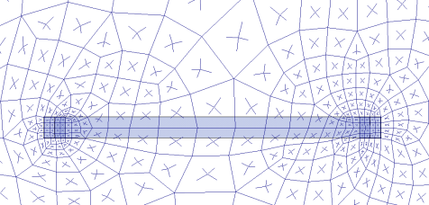
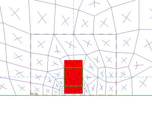
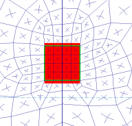
Column Meshing
The top of the column will be submeshed and connected to the surrounding plates with rigid links in a 12" x 12" square. This approach is more accurate than modeling the column connection at only one node. When only one node is used the slab will have a higher peak moment and higher deflection at that one point. Instead the rigid links create a rigid region over the top of the column that approximate the stiffness of the column attachment to the slab. The size of the rigid links will not change based on the column dimensions as this is only approximate. In most cases there will be 4 plates inside the rigid links.

The column node will connect to the slab via the additional diagonal rigid links. After the slab is meshed, additional diagonal rigid links are drawn to connect the column node to the square rigid links (shown below). The column node has rotational and translational support so there will be vertical and rotational constraint at the column location.
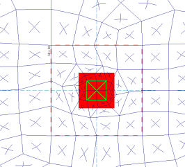
In most cases, the column node will land inside the 2x2 plate mesh in the same location as a plate corner. However, in certain edge and corner situations, as well as beam intersections, the column node will not align with the plate corners.
|
|
|
Edge Column |
Beam Intersecting a Column |
Slab Stiffness Considerations
Cracked Slabs
Selecting a Deflection Method of I Cracked/Elastic

Click on image to enlarge it

Click on image to enlarge it
The Icr factor default is set to 0.25 per ACI 318-14 Section 6.6.3.1.1 (ACI 318-11 Section 10.10.4.1). You can modify this factor with any value between zero and 1.0 by typing in this field. The Icr factor adjusts the stiffness of the plate elements comprising the slab by altering the thickness during solution. This adjusted thickness does not, however, affect design values (reinforcement calculations).
Service Checkbox
The Service checkbox in Load Combinations- Design tab currently only applies to Concrete Floor Slabs in RISAFloor ES.

Click on image to enlarge it
The commentary in ACI 318-14, Section 6.6.3.1.1 (ACI 318-11 Section 10.10.4.1) recommends a 1.43 factor to be applied to the cracked moment of inertia for all service loads. The program applies this factor to all Load Combinations that have the Service checkbox checked, as long as the Use Cracked Slabs is selected in the Model Settings in RISAFloor. This results in an effective default slab moment of inertia of (0.25)*(1.43)*Ig = 0.3575*Ig