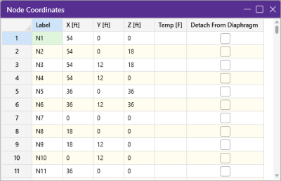
Node
Coordinates Spreadsheet
The Node Coordinates spreadsheet
records the node coordinates and ambient temperatures for the nodes
and may be accessed from the Spreadsheets tab  Data Entry icon
  Node Coordinates.
Click on image to enlarge it
Node Coordinates - columns
|
Column |
Description |
|---|---|
|
Label |
Label is used to assign a unique name (label) to every node. You can then refer to the node by its label. Each label has to be unique, so if you try to enter the same label more than once you receive an error message. As you create new lines, the program automatically creates a new, unique label for each node. |
|
X, Y and Z |
These three columns contain the coordinates of the node in each of the global directions. These represent the relative offsets of the nodes from the origin of the coordinate system (0, 0, 0). The appropriate units are listed at the top of each column. |
|
Temp |
Temp (Temperature) is used to define the ambient, no-stress, temperature at the node. Temperature loads are then calculated based on the differential between the ambient temperature interpolated across the member, and the applied thermal load. See Loads - Thermal Loads for more information. |
|
Detach From Diaphragm |
Detach From Diaphragm is used to detach nodes from a diaphragm. See Diaphragms - Modeling Tips to learn more about this. |
|
Round Off Coordinates |
Another option is ‘Round Off Coordinates’, which when selected, rounds off all the node coordinates to 1, 2, or 3 decimal places. It’s useful for models that have been created using generation functions or DXF files where a high number of decimal places is present for some of the coordinates. |
Several options on the Modify ribbon help you work with nodes. Selecting Relabel All or Relabel Selected lets you define a prefix to be used for the node labels before creating a new label for each node by using this prefix with a sequential number. For example, if you were to enter a prefix of “FLR”, the first node would get label FLR1, the second one would get FLR2, etc.
