Beams
RISAFoundation uses a Physical Member that is automatically sub-meshed into general-purpose beam elements. Beam data may be viewed and edited in two ways: graphically in a model view or in the Beams Spreadsheet. For descriptions of the beam data, see the Beams Spreadsheet section. Concrete design parameters are recorded on the Concrete tab of the Beams Spreadsheet, discussed in Beams - Design.
Draw Beams
To create new beams, you can draw them using a Drawing Grid, Project Grid or drawing point-to-point clicking existing nodes. You can set all of the beam properties up front, or you can modify these properties after you draw the beam. Graphically modifying properties is discussed in the next section.

Click on image to enlarge it
To draw beams:
- If there is not a model view already open, go to the View ribbon.
- Click the Open 3D Views icon in the Window section to open a new view.
- If you are not drawing between existing nodes, you need to create a drawing grid or define nodes in the Node Coordinates Spreadsheet.
- Go to the Home ribbon.
- Click the Beam icon in the Draw Elements section.
-
In the Properties panel, set the beam properties.
-
To start drawing beams, click on nodes or grid intersections with the left mouse button. The coordinates of the closest node or grid intersection to your cursor are displayed on the screen near your cursor.
The first click defines the Start Point of the first beam. The second click, and each click thereafter, defines the End Point of the first beam and also the Start Point of the next beam so that you can continue to draw. To stop drawing, click the right mouse button. You can then start drawing somewhere else with the left button.
The new beams are shown on screen and recorded in the Beams Spreadsheet.
- To stop drawing altogether, click the right mouse button again or press the Esc key.
- You may also specify or edit beams in the Beams Spreadsheet.
- You may undo any
mistakes by clicking the
 Undo icon in the Quick Access toolbar.
Modify Beam Properties
There are a number of ways to modify beams. You may view and edit the beam data in the Beams Spreadsheet. You may also click a single member or select multiple members to view and edit the properties in the Properties panel. You can use the tools in the Modify tab to graphically modify the beams in the 3D View.
In this section, we discuss the Properties panel for beams, which lets you modify the properties of beams that already exist in your model. For more information about selecting elements, see Graphic Selection.
To Modify Beams
To modify beams properties:
- If there is not a model view already open, go to the View ribbon.
- Click the Open 3D Views icon to open a new view.
- Click a single beam, or select multiple beams that you wish to modify.
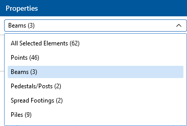
- If you have multiple elements selected, specify which element type to view properties for using the Selection Properties drop-down in the Properties panel.
-
Set the parameters for the beams within the Properties panel.
If certain properties vary within your selection of beams, the input field will show 'Various'.
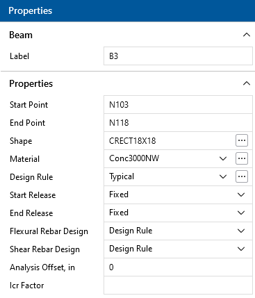
Beam Properties
The beam label displays at the top of the Properties Panel. Below this are the general properties where you can specify beam parameters, such as end releases, material and shape size.
Beams Spreadsheet - General Data
The Beams Spreadsheet records the properties for the beam elements and may be accessed by selecting Beams from the Data Entry drop-down on the Spreadsheets tab of the ribbon, or by clicking Beams from the Data Entry section of the Explorer panel.

Click on image to enlarge it
The following data columns hold the General data for the beams:
Beam Labels
You may assign a unique Label to any or all of the beams. You can then refer to the beam by its label. Each label has to be unique, so if you try to enter the same label more than once, you will get an error message.
Beam Start and End Points
The Start Point and End Point entries define the start and end locations of the beams using node labels.
Shape
The Shape entry is used to set the beam size. To enter a shape, type the shape name directly or click the  (ellipsis) button in the cell to access the Shape Selection dialog. For more information, see Beams - Database.
Material
The Material column displays the concrete material used for each beam. Available materials can be selected from the drop-down list, which contains all entries in the Materials spreadsheet. For more information, see Material Properties.
Design Rules
The Design Rules entry displays the selected design rule for each beam. Available design rules may be selected from the drop-down list, which contains all entries in the Design Rules Spreadsheet. For more information, see Design Optimization.
Start and End Releases
The Start and End release columns allow you to set the beam end releases to Fixed or Pinned. This determines how the beam connects to other elements at the end nodes.
Analysis Offset
This is a positive value that moves the beam downward in relation to any other element in the model. This not just a graphics change; the program is internally adjusting the location of the beam and connecting it to surrounding elements with rigid links. You can expect to see different distribution of forces due to the offset.
Beams Spreadsheet - Concrete Data

Click on image to enlarge it
The following data columns hold the Concrete data for the beams:
Icr Factor (Cracked Moment of Inertia Factor)
The Icr Factor is used to reduce the bending stiffness of beams. If this entry is left blank, the Icr factor defaults to a value of 0.35.
Service Level Stiffness
Due to cracking and material non-linearity, modeling the stiffness of concrete members is more complex than it is for steel or wood members.
For typical applications, ACI 318-14 Section 6.6.3.1 (ACI 318-11 Section 10.10.4) requires that member stiffness be reduced to account for the cracking that occurs when a member is subjected to ultimate level loads. As described in the previous section, RISA uses the Icr Factor to account for this stiffness reduction. However, for service level analysis, the level of cracking will be significantly less. Therefore, the stiffness used in your analysis should be representative of the reduced loading and reduced cracking. Per ACI 318-14 Section R6.6.3.1.1 (ACI 318-11 Section R10.10.4.1), the program accounts for this increased stiffness by applying a factor of 1.43 to the cracked section properties for any load combination that has the “Service” flag checked in the Load Combinations Spreadsheet.
Flexural Layout
The Flexural Layout entry displays the selected custom rebar layout for beam flexural reinforcement. When the Flexural Rebar Design column is set to Custom, available layouts can be selected from the drop-down list which contains all Bending Rebar Layouts from the Rebar Layout Database. For more information, see Custom Rebar Layout Database. When Design Rule is selected in the Flexural Rebar Design column, RISAFoundation will select the reinforcement for the beam based on the specified design rule.
Shear Layout
The Shear Layout entry displays the selected custom rebar layout for beam shear reinforcement. When the Shear Rebar Design column is set to Custom, available layouts may be selected from the drop-down list, which contains all Shear Rebar Layouts from the Rebar Layout Database. For more information, see Custom Rebar Layout Database. When Design Rule is selected in the Shear Rebar Design column, RISAFoundation will select the reinforcement for the beam based on the specified design rule.
Physical Members
Physical Members provide fixity to all joints that occur along the length of the member, without breaking that member into multiple smaller members. You may use the physical member feature to avoid defining one 'field' member with multiple members in your model. This saves time in building and editing your model and in understanding your results.
Continuous beams are examples of continuous 'field' members that can be modeled with one Physical Member. You may define them from start to finish without having to explicitly define their connection to other elements or boundaries through intermediate points. Subsequently, when it comes time to make changes to a beam you can edit the properties of one Physical Member rather than the multiple beams that might otherwise represent it.
Physical Members are also effective in managing results because the results for one Physical Member are reported together in the results spreadsheets and the beam detail report.
For additional advice on this topic, please see the RISA Tips & Tricks webpage at risa.com/post/support. Type in Search keywords: What are Physical Members?