Boundary Conditions
Boundary Conditions define how the model is externally constrained. The soil regions you define create a grid of compression-only springs to support your slabs/footings. You may define additional points of support as completely restrained or as partially restrained with a Spring. You can also define a spring support that has stiffness in only one direction with tension-only or compression-only springs.
Points of support may also be defined as Footings, Piles or Pile Caps. This section will deal primarily with points of support not at a footing, pile or pile cap. For more information on support at foundation elements, see Footings - Design and Piles and Pile Caps.
For additional advice on this topic, please see the RISA Tips & Tricks webpage at risa.com/post/support. Type in Search keywords: Boundary Conditions.
Creating and Modifying Boundary Conditions
There are a number of ways to create or modify boundary conditions. You may view and edit the data in the Boundary Conditions Spreadsheet, click a node to view and edit its properties, or you can use the Boundary Conditions tool to graphically assign or modify large selections of boundary conditions.
Modify Boundary Conditions for Nodes
The graphical Boundary Conditions tool discussed here lets you specify and modify boundary conditions graphically.
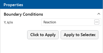
The parameters shown below are the same as those in the Boundary Conditions Spreadsheet and are described in Boundary Condition
Options. Use the  (ellipsis) button to select the boundary condition.
Click on image to enlarge it
-
If a model view is not already open, click the Open 3D Views icon on the View ribbon to open a new view.
-
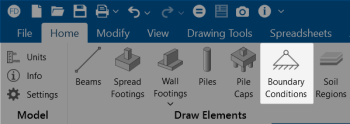
Click the Boundary Conditions icon on the Home ribbon (as shown in the following image) and select a boundary condition.
Click on image to enlarge it
-
You can apply the boundary condition by choosing Click to Apply or Apply to Selected.
To choose nodes individually, choose Click to Apply. Click the nodes with the left mouse button.
To apply the boundary condition to a selection of nodes, choose Apply to Selected.
- To apply more boundaries with different conditions, press the Boundary Conditions button once more.
- You may also view and edit boundary conditions by clicking on a node and editing the values in the Properties panel.
- You may also specify or edit boundary conditions in the Boundary Conditions Spreadsheet.
- You may undo any
mistakes by clicking the Undo
 button.
Auto-Generated Soil Springs
When a solution is performed, RISAFoundation auto-meshes each slab into a mesh of plate elements. In the process, points are automatically created to define the corners of each plate. A Soil Spring, or compression-only spring, is auto-generated at every plate corner point, in each slab. User-defined supports previously applied to any point within a slab will override any soil springs generated by the program. In other words, a soil spring will NOT be applied at those particular points in the slab.
RISAFoundation calculates the tributary area for each plate corner point individually and multiplies that area by the Subgrade Modulus defined in each particular Soil Region to determine the spring stiffness for the soil spring at that point. For more information, see Soil Springs Calculation.
Boundary Conditions Spreadsheet
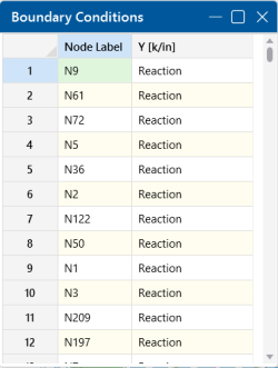
The Boundary Conditions Spreadsheet records the boundaries for the nodes and may be accessed by selecting Boundary Conditions from the Data Entry drop-down in the Spreadsheets ribbon, or by selecting Boundary Conditions from the Data Entry section in the Explorer panel.
Click on image to enlarge it
Click on image to enlarge it
The Node Label column contains the label of the node that is restrained.
The boundary conditions are entered in the remaining column by selecting
the cell, clicking  (ellipsis) button and choosing from
the boundary options. You may also type them in directly.
Boundary Condition Options
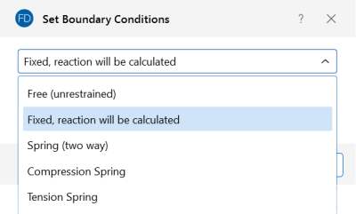
Free nodes have no restraint in any of the degrees of freedom and do not need to be listed on the Boundary Conditions Spreadsheet. The following are the valid boundary condition options that may be used.
Click on image to enlarge it
- These options are only available for nodes not defined by a footing, pile or pile cap.
- Models that contain compression-only or tension-only springs must be iterated until the solution converges. Convergence is achieved when no more load reversals are detected in the springs. During the iteration process, each spring is checked, and if any springs are turned off (or back on), the stiffness matrix is rebuilt and model is resolved.
- With this iteration procedure it is possible to run into a phenomenon known as "clapping". This occurs when a compression-only spring keeps going between a tension force present (where the spring is removed) to a compression force present (where the spring is re-added). This can be somewhat common in non-linear solutions. If you run into this phenomenon, you may see the program give Error 1162. The fix for this is to very slightly adjust either the loading or the spring/element stiffness to get the offending spring out of the range where it can bounce back and forth. Another option would be to move the location of the soil spring slightly so it's not right at an inflection boundary.
Reaction Boundary Condition
Reaction specifies full restraint for the vertical direction. No movement will be allowed in the vertical direction, perpendicular to the XZ plane, for the node and the reaction force will be calculated.
Spring Boundary Condition
The "Snnn" code for Springs models a spring attached to the node in the vertical direction. The "nnn" portion of the code is the numerical magnitude of the springs' stiffness. The appropriate units are shown at the top of the column.
For example, if a spring with a stiffness of 1000 Kips per Inch were desired in the vertical direction at a node, you would enter 'S1000' for the boundary condition.
Compression-Only Springs
The "CSnnn" code for Compression-Only Springs models a one way "compression-only" spring attached to the node in the vertical direction. This spring has stiffness for negative displacements (downward) and NO stiffness for positive displacements (uplift). The "nnn" portion of the code is the numerical magnitude of the springs' stiffness. The spring stiffness units are the same as those for a normal spring. Compression-only springs are used by RISAFoundation when auto-generating soil springs for slabs.
For example, if a compression-only (CS) spring with a stiffness of 500k/in were desired in the vertical direction at a certain node, you would enter 'CS500' for the boundary condition support.
This means that all displacements at this node in the downward direction will be resisted with a stiffness of 500k/in. However, the node is free to move in the upward direction.
Tension-Only Springs
The "TSnnn" code for Tension-Only Springs models a one way "tension-only" spring attached to the node in the vertical direction. This spring has stiffness for positive displacements (uplift) and NO stiffness for negative displacements (downward). The "nnn" portion of the code is the numerical magnitude of the springs' stiffness. The spring stiffness units are the same as for a normal spring.
For example, if a tension-only (TS) spring with a stiffness of 500k/in were desired in the vertical direction at a certain node, you would enter 'TS500' for the boundary condition.
This means that all displacements at this node in the upward direction will be resisted with a stiffness of 500k/in. However, the node is free to move in the downward direction.


