Model Settings
The model settings may be accessed on the Home ribbon in the Model section. The settings consist of three main options (Units, Info and Settings) that are highlighted in the following image.

Click on image to enlarge it
-
Units: The ‘Units’ option allows you to set the type of units (imperial, metric or both) you want to use in your model. Refer to the Units topic for more details on the units settings.
-
Info: The ‘Info’ option allows you to enter descriptive information, such as a title for the particular model being defined, the name of the designer and a job number. The title may then be printed at the top of each sheet of the output, and on the graphic printouts of the model.
-
Settings: The ‘Settings’ option provides control for most of the model-specific settings. These Model Settings are specific to the model that is currently open. The information stored here is retained with the model and will be retained even if the model is opened on a different computer.
You can save any of the Model Settings as the default setting, such that new models you create will begin with the settings you saved as Defaults. To do this, simply enter the information that you want to save and check the Set as Default box (see the image under the Solution heading for the location of this check box).
Project Information

Click on image to enlarge it
-
Project Notes is intended for information about the model that may be useful for the engineer or reviewer to refer to. This box is limited to 4000 characters.
-
Checked By is intended for the model reviewer to initial upon completion of a model review. Their initials are then printed on each sheet of the output.
Settings
To open the Model Settings window, click the Settings option from the Home ribbon, as shown in the following image.

Click on image to enlarge it
Solution
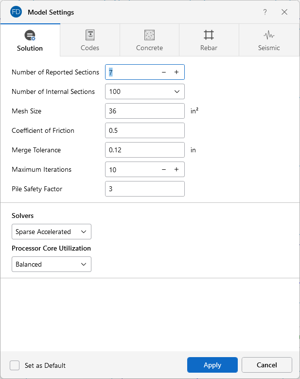
The Solution tab is the first tab in the Model Settings window. The entries on this tab are used to control settings that affect the general solution of the model.
Click on image to enlarge it
Number of Reported Sections controls how many places along each beam you receive reported beam force, stress and deflection results. This only affects the amount of data displayed in the Results Spreadsheets, and has no effect on the solution of the model or the code checks. For more information, see Printing and Beams - Forces.
Number of Internal Sections controls how many places along each beam the software calculates and stores results, such as deflections and code checks. The beam force diagrams displayed in the model view and the detail plot are also drawn from these results. Increasing this value means that the program will make more "cuts" along the beam's length, which means it is more likely to hit the theoretical maximum and minimum values for code checks.
The Mesh Size is used to control the coarseness or fineness of the slab mesh when RISA auto-meshes slabs during solution.
Coefficient of Friction is used in the slab sliding check to calculate the resisting force against sliding.
Merge Tolerance is used as the maximum distance two points can be apart and still be merged together. It is also used when scanning for crossing members and for unattached joints along the spans of beams.
Maximum Iterations defines the maximum number of iterations the program will undergo for tension and compression springs in a model. Soil regions are always modeled as compression springs, but piles may be tension springs, compression springs or both. In the first iteration, the program assumes a compression spring for every support node in the model. The program then checks the forces (tension or compression) in these springs against the soil moduli or pile stiffness. Soil springs have no tensile stiffness, and piles may or may not have tensile stiffness. If a support location sees tension, then the springs in this location are switched to tension springs of the appropriate capacity. Soil springs will have a tensile stiffness of zero and piles will have a stiffness defined in the Pile Definitions Spreadsheet. At this point, the model is re-run for its second iteration. The model is then checked again to make sure that tension springs are in tension and compression springs are in compression. If so, the solution is stopped. If not, the springs are updated to the proper tension or compression designation and the model is re-run again. At least three iterations are required to get acceptable behavior, though more may be needed in complicated loading scenarios.
Pile Safety Factor is used to calculate the static pile soil capacity. The user may modify this value to consider potential variances in soil and pile interaction.
- The Number of Reported Sections cannot exceed 20. Also, the Number of Internal Sections cannot be less than twice the Number of Sections. If unacceptable values are entered for either of these fields, the program will automatically reset them to acceptable values.
- When RISAFoundation is accessed from the Director for a model originating in RISAFloor or RISA-3D, the Beam Section Options will not appear. In these cases, the Model Settings from RISA-3D will control.
- You can check the Set as Default check box to have your settings saved for the next time you open the program.
Processor Core Utilization
Single lets you use a single core to run the model solution. This option is useful when you have several other computer programs that are CPU intensive running in conjunction with RISAFoundation.
Balanced lets you use half of the available cores on your computer to run the solution. This option will provide a faster solution time compared to using a single core, but will still allow half of your computer’s available cores to be used for other programs and computer processes.
Max lets you use all of the available cores on your computer, minus one. For instance, if you have eight available cores and select the Max option, the program uses seven cores in the processing of the solution. This option provides the fastest solution time, but still apportions a single core to be used for other programs and computer processes.
The Static Solver options are Standard Skyline or Sparse Accelerated. These can be selected from the drop-down menu in the Solvers section. See Solution for more information on these two options.
Codes
Click on image to enlarge it
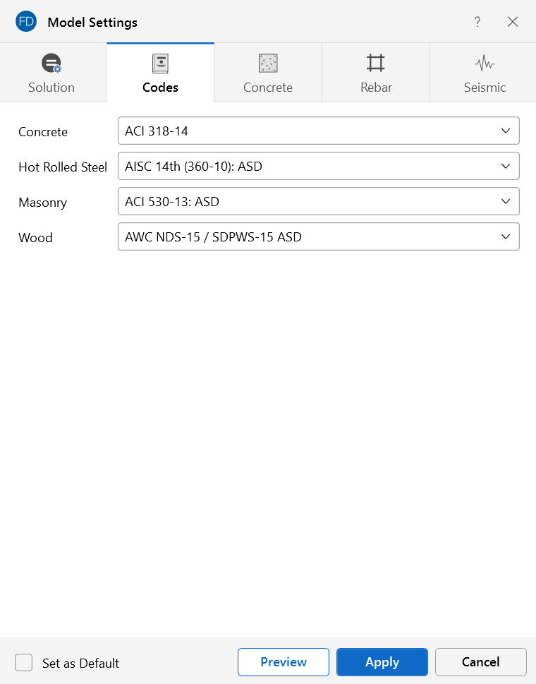
The settings under the Codes tab control which design code is used for code checks for each material type.
Concrete indicates which concrete code is to be used in the design of concrete elements.
Available options for concrete are:
- The 2022, 2019, 2014, 2011, 2008, 2005, 2002 and 1999 Editions of ACI 318
- The 1992 EuroCode (EC2) and the British publication of the 2014 and 2004 Eurocode (BSEN)
- The 2014 and 2004 Edition of the Canadian code (CSA-A23.3)
- The 2004 Edition of the Mexican code (NTC-DF)
- The 2007 Edition of the Saudi Building Code (SBC 304)
- ACI 318-08 and ACI 318-11 behave identically in the program, as there were no relevant changes between these two editions of the code.
- A significant change for the 2014 ACI code is a change to the minimum flexural reinforcement for mat slabs. Please see ACI 318-14 Sections 7.6.1 and 8.6.1 (and Chapter 13’s references to Chapter 7 and Chapter 8) for more information.
Hot Rolled Steel indicates which code is to be used for the design of hot rolled steel pile elements. The design code selected is used to calculate the tensile and compressive capacity for piles in the model.
Available options for hot rolled steel are:
- AISC 360-22 (16th Edition), 360-16 (15th Edition), AISC 360-10 (14th Edition), and AISC 360-05 (13th Edition) ASD and LRFD
- AISC LRFD (2nd and 3rd Editions)
- AISC ASD (9th Edition)
-
The CSA S16-14, CSA S16-09, CSA S16-05, CSA S16-01, and CSA S16.1-94 Canadian codes
Masonry indicates which masonry code is to be used for the design of masonry walls.
Masonry is only used for the wall in wall footing elements. For more information, see Wall Footing Definitions.
Available options for masonry are:
- The TMS 402-22: ASD and Strength Codes
- The TMS 402-16: ASD and Strength Codes
- The ACI 530-13: ASD and Strength Codes
Wood indicates which wood code is to be used for the design of wood pile elements. The design code selected is used to calculate the tensile and compressive capacity for piles in the model.
The available design codes for Wood are:
- The 2024, 2018, 2015, 2012 Editions of the NDS wood design code for ASD
- The 2014 and 2009 Editions of the CSA O86 Canadian wood design codes.
Concrete

Click on image to enlarge it
The entries under the Concrete tab contain options related to the analysis and design of concrete elements.
Compression Stress Block lets you choose what type of stress block to consider in your analysis. The options are the constant Rectangular Stress Block and the Parabolic Stress Block. For more information, see Parabolic vs. Rectangular Stress Blocks .
Parme Beta Factor is used to approximate the column’s 3D interaction surface for the PCA Load Contour Method.
Check the Optimize Footings check box to get simple spread footings to be sized for overturning and sliding forces.
The Use Cracked Sections check box will allow the program to use the cracked moment of inertia and reduce the bending stiffness of beams and slabs. The reduction factor can either be user defined by specifying the Icr Factor directly, or the program will automatically generate it using the program defaults.
Rebar

Click on image to enlarge it
Mat Slab Design Option offers a choice between two methods for the design of the mat slab rebar: namely, the Construction method and the Theoretical method. The Construction method, which has been the default method employed by the program for a significant period, determines the design of the slab based on an integer number of rebar. This method operates under the assumption that if the strip width divided by rebar spacing is not an integer, an additional rebar will be provided to guarantee the presence of a rebar at each end of the design strip. On the other hand, the Theoretical method is an added method that enables the program to calculate the rebar area based on the average value, where the rebar area equals As (single rebar) multiplied by the Strip Width divided by the Spacing. However, it is crucial to note that this method may not always result in an integer number of rebar, so unlike the Construction method, the results for the Theoretical method will have no info for the total rebar quantity.
Pedestal Min Steel allows you to choose the minimum percentage of reinforcing steel to be used in a concrete pedestal or pile section. The percentage entered will be multiplied by the gross area of the pedestal or pile section to determine the minimum amount of reinforcement required in each member. If left blank, the default minimum percentage of reinforcement steel will be used based on the selected concrete design code. For example, the default minimum percentage of steel for pedestals and piles is 0.5% under ACI 318-14.
Rebar Material Spec lets you choose from the standard ASTM A615 (imperial), ASTM A615M ("hard" metric, i.e. #8M is an 8mm bar), BS 4449 (British), prENV 10080 (Euro), CSA G30.18 (Canadian), IS 1786 (Indian), and AS/NZS 4671:2001 (Australian/New Zealand) reinforcement standards.
-
The rebar material specification in this section is for concrete design only. Masonry walls only support ASTM A615 rebar specification by default.
Checking the Leave room for horizontal rebar splices (2*d bar spacing) check box will allow a minimum spacing of one bar diameter between parallel bars. Otherwise, RISA will default to a two bar diameter or one inch clear spacing, whichever is greater, to allow for lap splices and continue to maintain adequate spacing between parallel bars. This option applies to beams only.
Checking the Include Welded Wire Reinf. (ASTM A1064) in Slab Design check box allows you to design a slab using Welded Wire Reinforcement.
Shear Reinforcement Options let you control the Number of Shear Regions that are used when detailing a beam span. You can also specify a Region 2 & 3 Spacing Increase Increment that you'd like the program to use when increasing or reducing the spacing of the shear ties.
- Welded wire reinforcement is only available for mat slabs, footings and pile caps.
- Only ASTM A1064 deformed bar sizes are available.
Seismic
The options on the Seismic tab list settings that are specifically related to calculation of code prescribed Seismic Loads. The input options you have depend on the Seismic Code selected.

Click on image to enlarge it
SDs represents the 5% damped spectral response design acceleration for short-period response. This will be used if you included vertical seismic load effects in your seismic load combinations.
(Ω) is the Overstrength Factor.
Redundancy Factor (ρ) is based on the extent of redundancy in your structure.
Each of these inputs can be included in the seismic load combinations generated by the LC Generator.