Pile Caps - Design
In this section, we will talk specifically about the calculations for pile caps. These design results are NOT available when using piles and a slab to create your pile cap. The only portion of this section that is applicable to individual piles is the Pile Punching Shear section. For slab/pile cap design, see Slabs.
Pile Cap Design Philosophy
Pile cap design within RISAFoundation considers beam philosophy, as opposed to truss philosophy. Both are acceptable by code (ACI 318-14 Section 13.4.2/ACI 318-11 Section 15.5.3).
Pile Capacity Checks
These checks allow the engineer to see if any of the piles in the model are exceeding the allowable pile forces.
Allowable Pile Loads
The allowable pile loads are defined by the user for general piles in the Pile Definitions Spreadsheet. For hot rolled steel, concrete and wood piles, the program calculates the axial capacity based on the pile and material properties. If the piles are part of a pile cap element, these allowable loads are reduced by the reduction factors entered on the Pile tab of the Pile Cap Definitions Spreadsheet.
Loads Developed in Piles in Pile Cap Applications
The loads developed in the piles within the pile cap elements are found using the equations below. Some things to note on the computation of these forces:
- Loads are only applied to the cap at the pedestal location, which is placed at the centroid of the cap.
- The axial pile stiffness (given in the Pile Definitions Spreadsheet) is considered the same for both compression and tension and is taken from the Comp. Stiffness entry.
- The pile cap is assumed to be rigid.
- The centroid location for force calculations of the piles is from the mid-height of the pile cap.


where:
Ppile = Total axial load on an individual pile
P = Column load, self-weight of the pile cap, pedestal and overburden
N = Total number of piles in pile cap
Mx,z = Applied moment to pedestal
xp, zp = Distance from centroid of pile cap to centroid of individual pile parallel to the respective axis
Vx,z = Applied shear to pedestal
hped = Height of pedestal from the top of the pile cap
d = Thickness of pile cap
T = Applied torque to pedestal
 = Angle between the centroid of the column and the centroid of the pile location, taken from the negative local x direction counter-clockwise
Vpilex: Shear in pile in local x direction
Vpilez: Shear in pile in local z direction
Vpile: Total demand shear in pile (in any direction)
Pile Cap Flexural Design
The flexural design of pile caps is based on the moment at the face of the pedestals in each direction. The image below explains how the design moment, Mu, is evaluated.
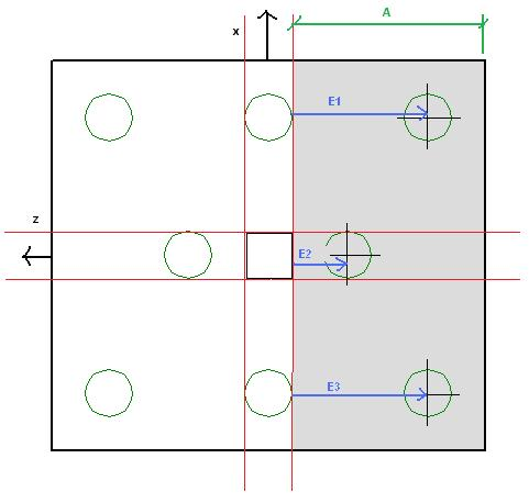
The red lines in the image show the locations where we compute the moments in the pile cap. The calculation of the moment at the face of pedestal is as follows:

Thus, the program uses the factored pile forces multiplied by their horizontal distance to the face of pedestal and subtracts the self-weight of the pile cap and overburden in this area multiplied by its moment arm. In the example shown above, this would be the Muxx moment at the right face of the pedestal. This calculation would then be done for the left face of the pedestal and the enveloped maximum positive and negative moments are given.
This calculation is then carried out identically in the Muzz direction.
Flexural Reinforcement Design
The design of reinforcement runs through a design routine, which is described below, to come up with the area of steel required in both directions. This routine checks the area of steel based on flexure and then checks minimum requirements. The routine also considers the short side amplification factor, as well.
As req'd = area of steel required for the design moment, using typical bending equations.
- If Astop req’d > .0033bd use Astop req’d. This is exactly the same for Asbot.
- If Astop req’d < .0033bd < 4/3As, use 0.0033bd. This is exactly the same for Asbot.
- If 4/3As top req’d < .0033bd, use4/3As. This is exactly the same for Asbot.
- Check for amplification of As in the short direction considering the β factor. See below for more information.
- After these steps compare:
- ACI 318-14: As top to 0.0018bh and As bot to 0.0018bh. If both are greater than 0.0018bh then you are done. If less than 0.0018bh, steel is added to meet this requirement for each face.
- ACI 318-11: As top + As bot to 0.0018bh. If greater than 0.0018bh then you are done. If less than 0.0018bh, we simply take the area of steel that needs to be added and add half to the top and half to the bottom.
- The final check would be to compare the steel ratios to the min and max ratios from the Pile Cap Definitions - General tab.
- If the user-defined steel ratios do not meet code requirements we will use the code requirements and provide a note in the Detail Report.
- β Factor consideration
- β = ratio of long dimension of pile cap to short dimension of pile cap.
- Asβ = As req'd*(2β )/(1+β)
- For pile caps with clipped corners we are taking the full dimension for the β calculation.
- If no flexural reinforcement is required in a given direction, all of the shrinkage and temperature steel in that direction will be added to the bottom of the slab.
- If top reinforcement is required in one direction and bottom reinforcement is required in both directions, then all provisions may be satisfied without giving top reinforcement in the direction where reinforcement is not required. We currently do not reinforce this opposite direction, though it is recommended to do so.
d Calculation
For bottom bar reinforcement design:
d = tslab - pile embed - bot cover - dbot bar
For top bar reinforcement design:
d = tslab - top cover - dtop bar.
- Because we do not know exactly how the reinforcement will be placed, we take the interface of the two directions of reinforcement as the location for the d calculation.
- The Embedment Depth field is only used to calculate "d" with Pile Cap entities. If you are using slabs with pile supports, this embedment depth is not considered for the slab design - though it is still considered for the punching shear check. For slab entities d = tslab - bot cover - dbot bar. Therefore, the bottom cover must include the embedment depth of piles for models with slabs supported on piles, but not for pile cap entities.
Pile Location Tolerance Consideration
If there is a pile location tolerance defined, we simply modify the Mu equation above by adding the tolerance to the moment arm for each individual pile. This will nearly always increase the moment demand.

One Way (Deep Beam) Shear Check
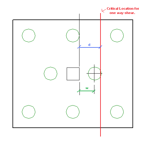
This check considers the entire pile cap as a beam element and checks the overall shear across the pile either at a distance d from the face of the pedestal, or at the face of the pedestal. The location of this check depends on the distance, w, where w = the distance along the local axes from the face of pedestal to the centerline of the nearest pile in that direction.
If d < w, the critical location where shear is checked is taken at a distance d from the face of the pedestal. In this case, the equation for the shear stress capacity is found by:

ACI 318-14 Table 22.5.5.1/ACI 318-11 Equation 11-5
If d > w, the critical location where shear is checked is taken at the face of support.
 ;
;
CRSI Design Handbook 2008 Eqn 13-2 on P.13-26
![]()
The equation to calculate the shear capacity is:

(φVnmax only applies for eqn 13-2)
where:
Mu = enveloped moment at critical location.
Vu = enveloped shear at critical location
ρw = Asprovided/bd
d = tslab - pile embed - cover - dbar
We do these calculations for both sides of the pedestal in both directions and envelope the worst code check in each direction.
Considerations
- Mu and Vu are the enveloped moment and shear values. The maximum moment and shear occur at the same location for the majority of cases.
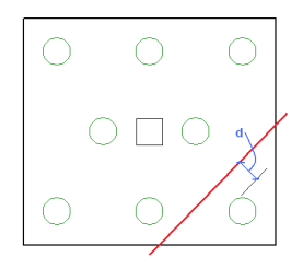
- We are NOT considering the one-way beam shear failures that can occur in other locations within the pile cap. An example of this type of failure would be a shear force that might shear off a corner of the pile cap.
- For lightweight concrete, the lambda reduction factor specified in the Materials Spreadsheet is applied to the capacity per ACI 318-14 Section 22.5.6.1 (ACI 318-11 Section 11.2.1.2).
Pile Location Tolerance Considerations
When a pile location tolerance is defined, that tolerance is simply added to the 'w' term in each direction. An increased value for 'w' will decrease the one way shear capacity of the pile cap.
Code Considerations
For the Saudi Code, ACI 318-05 is used. This is noted in the Detail Report. The Mexican and Canadian codes are simply using their standard beam and slab one-way bending equations.
Pile Punching Shear Checks
The punching shear in a pile is simply the axial compression force in a pile considering strength load combinations.
The punching shear capacity is obtained via the ACI code equations. The code requires this value to be the minimum from the equations below.


- When ACI 318-19 is selected, an additional size effect factor, λs, is added in the above equations. λs is a function of the effective depth of the slab 'd', and is calculated per Equation (22.5.5.1.3).
- For lightweight concrete, the lambda reduction factor specified in the Materials Spreadsheet is applied to the capacity, per ACI 318-14 Section 22.5.6.1 (ACI 318-11 Section 11.2.1.2).
bo Calculations
The calculation of bo is done considering an interior, edge and corner condition. The program calculates a bo value for each of these conditions for each pile and then uses the minimum value. The interior, edge or corner condition that resulted in the minimum value is also reported.
When there is no reinforcement at the top face of the pile cap (in either direction)
If there is no reinforcement in the top of the pile cap, the slab is considered unreinforced for pile punching shear. Because of this, we use the plain concrete provisions from ACI 318-14 Chapter 14 (ACI 318-11 Chapter 22). From ACI 318-14 Section 21.2.1 (ACI 318-11 Section 9.3.5), the ϕ factor for shear is 0.60 (as compared to 0.75 for reinforced concrete). The punching shear equation for structural plain concrete (ACI 318-14 Table 14.5.5.1/ACI 318-11 Equation 22-10) is the reinforced punching shear equations with a 2/3 factor applied. Thus, the ratio of using structural plain concrete to reinforced concrete is: 2/3*(0.55/0.75) = .488. RISAFoundation rounds this to 0.5 and takes a 50% reduction in capacity for punching shear if there is no reinforcement in the top of the slab.
When the Pile's Local Axes do not correspond to the slab geometry
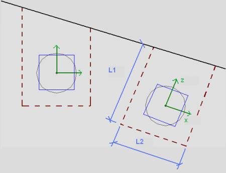
The punching shear perimeters are always investigated with respect to the pile local axes. As shown below, there may be cases where these local axes do not correspond to the cap edge or corner geometry adjacent to that pile. In cases like these it is possible for this to result in an artificially large assumed punching shear perimeter.
Using Equivalent Square Piles
When calculating the punching shear perimeter for a round pile, the program always converts the pile into an equivalent square pile of equal perimeter (similar to the super-imposed square in the image below). This greatly simplifies the calculation of punching perimeters when close to an edge or corner.
d Calculation
d = tslab - pile embed - top cover - dtop bar
Group Punching for Piles
We do not currently calculate a group punching check. At solution we will check to see if closely spaced piles have shear perimeters that overlap. If so, we will give a warning in the Warning Log noting this. We will still give the capacities assuming the total shear perimeter for the pile not considering group action.
Beams/Pedestal Intersecting the Shear Perimeter of a Pile
- When a beam is co-linear with the pedestal joint, the program will not provide a punching shear check on the pedestal. In these cases, a code check of "NC" will be listed.
- The program does not specifically check for instances where the pedestal for the pile cap is located within the pile's shear perimeter. Thus, the punching shear capacity will be calculated as if there is no pedestal above.
Pedestal Punching Shear Checks
Pedestal punching shear checks are handled in much the same way that pile punching shear checks are considered. A major difference is that pedestals can transfer moment into the pile cap. Thus, the pile cap punching shear capacity is reported as a stress and the maximum stress induced due to axial load and moment is checked. For more information, see Pile Cap Results.
To calculate the shear demand at the pedestal, simply sum the factored axial forces in the piles outside of the pedestal shear perimeter and add to that the factored self-weight of the pedestal and a ratio of the factored self-weight of the pile cap.

d Calculation:
d = tslab - pile embed - bot cover - dbot bar
When Piles intersect the Shear Perimeter of the Pedestal
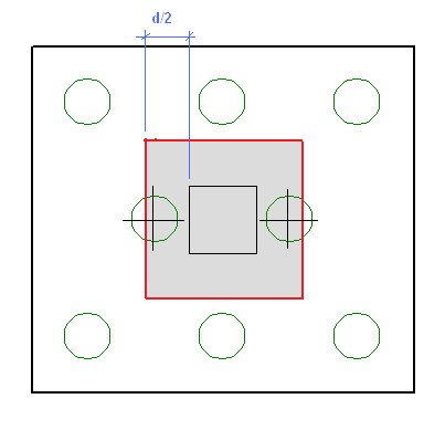
At solution the program checks to see whether any of the piles in the pile cap have their centerlines located within the shear perimeter of the pedestal. If so, these piles do not contribute to the pedestal punching shear demand in the cap. If this centerline falls outside of the shear perimeter the entire force of the pile adds to the pedestal punching shear demand.
Pedestal Design
Pedestal design for pile caps is identical to what is done for pedestals on slabs. For more information, see Pedestals-Design Results.
Pile Design
Pile design for pile caps is identical to what is done for individual piles. For more information, see Pile Results.