Crack Width Settings
The program allows you to specify a limit for crack widths. If the calculated width exceeds the limit defined by you, the program will add reinforcement to limit the crack width as per design code provisions. The calculated rebar is included in the “service” envelope of reinforcement. The calculation of crack width will be available as an option when the selected design code does not require limitations for crack width. You can select to only report crack width, or to report and limit crack width, in which case the program adds reinforcement if required. After analysis and design,you can View Crack Width Contour Results. For the description of crack width settings in this help menu, the ACI code was chosen.
Note: Crack widths for ACI code are calculated using EC2 code provisions.
To set the crack width settings:
-
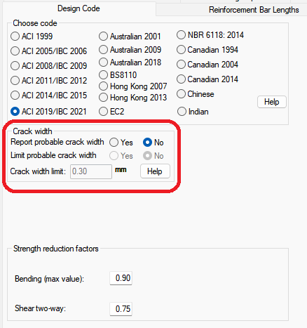
Go to Criteria>Design Criteria and click on the Design Code  icon (if the program has been opened in RC only mode) or click on the Allowable Stresses
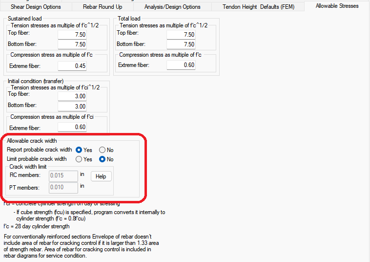
  icon (if the program has been opened in PT/RC mode).
Note: You must have One-Way criteria or Beam Criteria selected in the Criteria pane for the options for Allowable crack width to be visible.
Design code window:
Click image to enlarge
Allowable stresses window:
Click image to enlarge
-
Depending on the selected design code, you will have an option to enter the allowable crack width or to report crack width only. Select the options you want to use for the Allowable Crack Width. Descriptions of these options can be found in the Criteria-Design Code topic of this help menu.
-
Click OK to apply the settings to the model.
-
You can then run the Analysis, Design the Sections, and View Crack Width Contour Results.