Aluminum - Design
Full code checking can be performed on standard aluminum shapes, based on the following codes:
-
Aluminum Design Manual 2015: Building and Bridge
-
Aluminum Design Manual 2010: Building and Bridge
-
Aluminum Design Manual 2005: Building and Bridge
Aluminum properties are available in the database and the values are based on the ADM values (See Aluminum Database). You can also input your own basic shapes and the properties will be calculated automatically.
Design Parameters
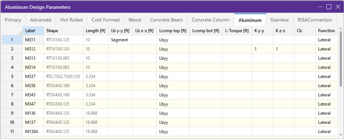
The Aluminum tab on the Members Spreadsheet records the design parameters for the aluminum code checks. These parameters may also be assigned graphically. See Modifying Member Design Parameters to learn how to do this.
Click on image to enlarge it
These parameters are defined for each aluminum member. The entries are explained below.
Label
You may assign a unique Label to all of the members. Each label must be unique, so if you try to enter the same label more than once you will get an error message. You may relabel at any time with the Relabel options on the Modify ribbon.
Shape
The member Shape or Section Set is reported in the second column. This value is listed for reference only and may not be edited as it is dictated by the entry in the Section/Shape column on the Primary tab.
Length
The member Length is reported in the third column. This value may not be edited as it is dependent on the member end coordinates listed on the Primary tab. It is listed here as a reference for unbraced lengths which are discussed in the next section.
Unbraced Length
See the Unbraced Lengths topic.
K Factors (Effective Length Factors)
See the Unbraced Lengths topic.
Sway Flags
See the Unbraced Lengths topic.
Cm - Interactive Bending Coefficient
Cm Coefficients are described in Section 4.1.1 of the ADM code. If these entries are left blank, they will be automatically calculated.
The Cm value is influenced by the sway condition of the member and is dependent on the member's end moments, which will change from one load combination to the next, so it may be a good idea to leave these entries blank.
Cb - Bending Coefficients
For the aluminum codes, Cb Coefficients depends on the moment variation over the unbraced length as described in ADM Chapter F. If this entry is left blank, it will be calculated automatically.
Function for Stiffness Reduction
The Function entry may be set to either 'Lateral' or 'Gravity' using the drop down list in the spreadsheet. If the Adjust Stiffness option is set to Yes on the Codes tab of the Model Settings Dialog, then all members with a 'Lateral' Function will be considered for the stiffness reduction required per the Chapter C.2 Calculations of Required Strength.
The Flexural Stiffness Reduction of the Direct Analysis Method will be applied to all 'Lateral' members whose member type is set to either 'Beam' or 'Column' on the Primary Tab of the Members Spreadsheet. This process involves evaluating certain conditions:
-
Primary Stiffness Adjustment Requirements
The program first checks whether a member satisfies the three primary stiffness adjustment requirements:
-
The member is defined as “Lateral”.
-
The stiffness adjustment option is enabled for the specific material being used.
-
The chosen material code permits stiffness adjustment for the selected material.
-
-
Stiffness Adjustment Calculation
Once the above conditions are met, the software proceeds to calculate the stiffness adjustments for the member. This includes reducing the area and moment of inertia based on predefined multiplication factors:
-
Aluminum Material: Area and moment inertia are multiplied by 0.8.
-
-
Exclusive Criteria
However, certain exclusion criteria are considered to determine whether to apply the stiffness adjustments or not. The following conditions must be met simultaneously for exclusion:
-
The material is Hot Rolled
-
The selected steel code is AISC 13th ed.
-
The member type is not specified as:
-
Column or v-brace for area reduction.
-
Column or beam for moment of inertia reduction.
-
-
If all the exclusion criteria are met, the original area and moment of inertia values will be retained without applying the stiffness adjustment multiplication factors. This ensures that certain types of HR members, when using the AISC code, maintain their original stiffness characteristics.
The program can perform an iterative analysis during the solution depending on the value of τb. In this case, the stiffness matrix is recomputed for each iteration until the value of τb converges within 1 percent for all 'Lateral' members in compression. In the unlikely event that τb is less than zero, the value of τb is considered to be 1.e-5.
When the users sets the Adjust Stiffness flag on the Model Settings to Yes (Tau =1.0), then the program will use a Tau of 1.0 in the stiffness analysis and no iteration of the stiffness matrix is necessary. This option is a good feature for models which take a long time to solve or which have not yet been proportioned to control drift.
The Axial Stiffness Reduction of the Direct Analysis Method will be applied to all 'Lateral' members whose member type is set to either 'Column' or 'VBrace' on the Primary Tab of the Members Spreadsheet.
Aluminum Code Check
Access the Code Check spreadsheet
by selecting the Results tab  Envelope (or LC) button
  Code Check. Alternatively, on the Results toolbar you can select Code Check.
Click on image to enlarge it
The final results of the code checking are the code check values UC Max and Shear UC. So, if this value is less than 1.0, the member passes. If it is greater than 1.0, the member fails. If the value is greater than 9.999 it will be listed as "9.999". The Shear Check is based on fs/Fs. Note that torsional shear, if any, is also included in this check. The location for the shear check is followed by "y" or "z" to indicate the direction of the shear. The Loc field tells at what location the maximum code check occurs measured from the I-node location of the member.
The remaining columns provide some of the values used in the code check with the equation number itself given in the last column. The Member Detail Report gives more values used to perform the code check.
The final field lists the controlling equation for the code check. This will be one of the equations from Section 4.
For enveloped results the combination that produced the listed code and shear checks is given in the column "lc". The other values are the corresponding values and are not necessarily the maximums across all the combinations.
The moving load results are enveloped and the governing load combination and step location is shown for each result value under the "LC" column. The first number is the load combination, the second is the step number: (load combination - step number). See Moving Loads to learn more.
- The program currently only performs an analysis of double sections and does not perform a code check of any kind.
- The Member Detail Report gives more values used to perform the code check.
- See Spreadsheet Operations to learn how to use Find, Sort and other options.
- See Results View Settings - Members to learn how to plot member results.
Aluminum Detail Report
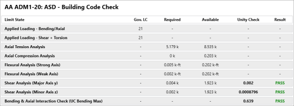
The aluminum detail report has design information for the specific code checks:
Click on image to enlarge it
The Max Bending Check is based on ADM Chapter H, with the governing Equation and Location listed.
The Max Shear Check is not provided in the ADM specification, this represents fs/Fs with the governing Location listed.
The Max Defl Ratio is based on the entire length of the member.
The Slender Limitl1 and l2 are calculated based on the Gov Eqn. The Slenderness Ratio are given based on the Design Aids in Tables 2-x ADM Section VI. The Slender. Ratio is also based on the Gov Eq , for further information refer to the ADM Design Aids.
Assumptions and Limitations
For all shape types, it is assumed that the transverse load on the member is occurring through the member's shear center. This means secondary torsional moments that may occur if the load is not applied through the shear center are not considered.
- Single Angles are not checked for bending in the 2005 and 2010 codes. They are checked for bending in the 2015 and newer codes.
- rye, effective radius of gyration from Eq 4.9.1-1 is used for doubly symmetric sections beams.
- Welded regions are not checked in RISA-3D. You can use the welded material properties for the entire member, or create segments that are welded material in order to check the weld properties. For additional advice on this topic, please see the RISA Tips & Tricks webpage at risa.com/post/support. Type in Search keywords: Welded Aluminum.
- Connections are not checked, including web crippling, fatigue or stiffeners.
- Kt in is assumed to be the smaller of Kyy or Kzz.
- Double Sections - The program currently only performs an analysis of double sections and does not perform a code check of any kind.
Special Messages
Aluminum Code Check Not Calculated
This message is displayed when the member is not defined with a database shape, is defined as a double section, or an Aluminum code is not specified on the Model Settings, or no units were specified.
-Pu was ignored in the calculation of the unity check-
This message is reported in the detail report when the member axial force is low (less than 5% of capacity). This is done so that beam members with very low axial forces will give similar code checks whether in tension or compression.


