Rigid Diaphragms
Rigid diaphragms represent a plane of very high rigidity. Rigid diaphragms distribute load to elements which connect to them solely based on the stiffness of the elements. They achieve this by tying all of the
- There is no rigid diaphragm design in the program. This is strictly an analysis tool.
- Sloped rigid diaphragms are not supported. Therefore, rigid diaphragms always exist in a flat horizontal plane.
Load Attribution
Loads applied within the plane of a diaphragm will be attributed to all elements which connect to the diaphragm. The amount of load which each element takes is proportional to its stiffness. Diaphragms are capable of both translation and rotation, so the torsional effects of the moment arm between the center of load and the center of rigidity are accounted for. This is also true for a dynamic mass which is offset from the center of rigidity.
Because a rigid diaphragm is part of the stiffness matrix, an explicit Center of Rigidity is not calculated or reported. Internally, the program creates a hidden set of rigid links which interconnect all of the

Click on image to enlarge it
Connectivity
All
Rigid Diaphragms must be defined along the Global Axes, therefore they can only exist in the XY, XZ, or YZ planes. If rigid behavior is desired along a plane other than these, a semi-rigid diaphragm (made of plates) with a large stiffness value can be used instead.
Rigid Diaphragm Stiffness
The stiffness of the rigid diaphragm is set to a unitless value of 1 x 10⁷ by default. This value has been calibrated as providing the best behavior for most models. It can be adjusted from within the diaphragms spreadsheet, however adjusting this value is only recommended in the following circumstances:
- The lateral stiffness of elements which pass through the diaphragm is sufficiently large to cause the rigid diaphragm to behave as a semi-rigid diaphragm (i.e. the translations of the
- The dynamics solver is not converging. In this case, try reducing the diaphragm stiffness to 1 x 10⁶, however, be sure to confirm that the diaphragm is not behaving semi-rigidly (see #1)
- The program has generated a warning that the sum of the reactions does not equal the total applied load. In the case of points on the diaphragm which have a very close proximity to each other, the stiffness of the internally generated rigid link between them may approach the stiffness of a boundary condition. If this happens, the model can have Ghost Reactions, which are points which act as boundary conditions (dumping load out of the model) without any notification. In this case try reducing the diaphragm stiffness to 1 x 10⁶. However, be sure to confirm that the diaphragm is not behaving semi-rigidly (see #1).
To adjust the diaphragm stiffness:
-
Open the Diaphragms spreadsheet from the Explorer panel or from the Data Entry list.
-
Right-click in the Diaphragms spreadsheet and choose Set Diaphragm Stiffness from the menu.
. Solution tab Advanced options:
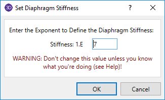
Rigid Diaphragms in a RISA-3D Only Model
With RISA-3D's diaphragm feature, a
Rigid Diaphragms in a Combined RISAFloor/RISA-3D Model
A RISA-3D model that is linked up to RISAFloor has an automatic rigid diaphragm analysis and design. Each individual slab/deck polygon is converted to a rigid diaphragm within RISA-3D. Therefore, it is possible to have multiple independent diaphragms at any given floor elevation.