Warning Log
Click on image to enlarge it
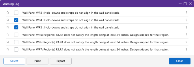
The Warning Log Spreadsheet provides you with a record of any warnings or errors that occurred during the solution of your model. The log should be reviewed for warnings or errors that would affect the design of your structure. The error log reports back the item label for which the error occurred.
-
Click the Help button to jump to the specific warning within the Warning Log section of the Help File.
-
Click the Find button to zoom into the specific element reported in the warning.
-
Use the Select checkbox and Select button at the bottom to select the elements reported for those particular warnings.
-
You can view the warning log by clicking on the Spreadsheets menu item and then clicking on the Warning Log selection.
-
Click the

The following sections include some of the common warnings which might require additional explanation.
Sum of reactions is not equal to the sum of the loads (LC xx)! Check for any small rigid links or fixed boundary conditions.
When the solution is complete, the program checks the sum of the reaction forces in each direction if this is more than 0.1% different from the sum of the applied loads, then this warning message will be displayed. The most common causes for this warning message are the following:
- A joint instability which has been automatically LOCKED by the program. If the joint is locked then the reaction at that location is not computed. Once you rectify the instability then this warning log message should also go away. You may also need to uncheck the "Lock isolated ROTATIONAL instabilities without notification" box as this may conceal some instabilities. See the Stability section for more information.
- A user assigned boundary condition which was used the "Fixed, reaction will not be calculated" option rather than the "Reaction" option. See the Boundary Conditions section for more information. Using the term "Fixed" suppresses the reaction output in the Joint Reactions and thus the applied loads does not equal joint reactions. In this case the Warning Log could likely be ignored, as there is a valid reason for this discrepancy.
- A "ghost reaction" may have developed where one or more rigid elements (Diaphragms, rigid end offsets, or rigid links) have become so stiff that they actually became stiffer than the internal stiffness used by the program to define boundary conditions. In this rare case forces may be leaving the model at locations other than boundary conditions. Having a combination of a rigid diaphragm, rigid links, rigid end offsets, top of member offsets, etc., all in a localized place in the model could cause these.
For additional advice on this topic, please see the RISA Tips & Tricks webpage at risa.com/post/support. Type in Search keywords: Sum of Reactions.
Warning Messages
The following table contains all possible warnings, their cause, and possible solution.
Warning Numbers
| Warning Number | Warning Log Message | Cause | Solution |
|---|---|---|---|
| WARNING 41001 | Web Slenderness > 70e. Web Buckling NOT checked for Shear Capacity. | British Hot Rolled Steel Design has been requested for a Hot Rolled Steel HHS Tube, Channel, or WT shape that has a very slender web. The current design code does not address web buckling as a failure state for shapes other than Wide Flange Members. | See if a code revision now provides guidance on checking web buckling for Tubes, Channels, or WT shapes. |
| WARNING 41003 | The rebar does not exist. No Capacity Calculated. | This message means that a user defined reinforcement profile has resulted in a member with zero capacity (and zero reinforcement) at the described location. | Revise the user defined reinforcement so that it is present at all locations along the member's length. |
| WARNING 41005 | Span length is less than 1 foot. No design for this span. | RISA uses span information to perform concrete member design and rebar optimization. When a member spans less than 1 foot from support to support then the program cannot perform this design. | Increase the span to a length greater than 1 foot, or ignore design of this member in this short segment. |
| WARNING 41007 | Composite design not done : Beam is continuous. | The composite beam has fixed ends, or passes as a continuous member over a support. This resulted in a negative bending moment on the beam, which would place the concrete slab in tension. RISA cannot perform a composite design when the slab is in tension | Modify the beam's end releases to be pinned, or eliminate a mid-span support under the beam. Otherwise, change the beam to be non-composite. For a T-beam member in RISA-3D seeing negative bending, the flanges will be ignored. |
| WARNING 41009 | Unable to provide min steel (As,min) per Model Settings. | A minimum area of steel was specified in the Model Settings. However, the cross section size, and the rebar spacing and cover requirements prevent enough rebar from being placed to meet that area of steel requirement. | Increase the cross section size of the member so that more steel can be placed, or lower the minimum area of steel requirement in the Model Settings. |
| WARNING 41011 | The tensile strain in steel is less than 0.004 | The arrangement and amount of reinforcing steel is such that if the member fails it will fail in a brittle manner (Compression Controlled Section)). This is not allowed, per ACI 318-14, Sections 7.3.3.1, 8.3.3.1, 9.3.3.1 (ACI 318-11 Section 10.3.5) | The quantity and arrangement of rebar is such that the rebar is not yielding prior to a concrete failure. Change the dimensions of the cross section of the concrete or alter the rebar design rules such that the rebar yields first. |
| WARNING 41012 | The tensile strain in steel is less than 0.005 | The arrangement and amount of reinforcing steel is such that if the member fails it might fail in a brittle manner (Transition Section). The strength reduction factor was reduced according to ACI 318-14, Section 21.2.2 (ACI 318-11 Section 10.3.4) | This does not indicate a failure. However, the full strength of the section is not being reached. To increase the strain (and therefore increase the strength), change the dimensions of the cross section of the concrete or alter the rebar design rules such that the rebar yields first. |
| WARNING 41021 | More than 800 bars not allowed. | The concrete column solver used by RISA for our direct integration solution has an internal limit of 800 flexural bars per concrete column. This limit has been exceeded for this member. | If using a custom rebar layout, reduce the number of bars. If doing rebar optimization, use a larger minimum bar size so the program will use fewer bars. |
| WARNING 41023 | Optimize concrete beam solver error. | The concrete beam solver has encountered an error. | Contact RISA Support and send your model so that this error can be resolved. |
| WARNING 41025 | Column/Beam Cover Value too large. 25% of member depth used instead. | The program's concrete solver was not designed to accommodate very large cover values relative the member depth/width. Therefore a maximum cover value of 25% of the member's dimension in that direction was used instead of the cover value specified in the rebar design rules. | Modify the member size or the cover dimension so that the cover dimension is no more than 25% of the member dimension. |
| WARNING 41027 | Unable to Iterate Phi for a Given Rebar Strain. | For the ACI-318 2002 Concrete Code and later, the Phi value for axial/flexural loading is based on the concrete strain, and must be iterated for the Load Contour method. This iteration process has failed for this particular member and load. | Send this model to RISA so we can review the conditions under which the value of Phi could not be calculated. |
| WARNING 41029 | Member/Wall is slender and can sway, but P-Delta Analysis was NOT run. | A slender concrete column or concrete wall panel has a Sway flag set in its Design Parameters , however a P-Delta analysis was not run in 1 or more Load Combinations that are set to do Concrete Design, so the expected amplifying effects were not calculated. | On the Load Combinations spreadsheet, set the PDelta value to be "Y" or "C" so that a P-Delta analysis is run for the Load Combinations that are flagged to do Concrete Design. Alternately, if the member or wall cannot sway, remove the Sway flag. |
| WARNING 41031 | Slender Compression Failure (Pu > .75Pc). No Slender calculations done. | The axial compression exceeds 75% of the Euler Buckling capacity of the member. This means that the member is prone to column-type buckling, and it causes ACI 318-14/19, Eqn 6.6.4.5.2 (ACI 318-11 Eqn 10-12) to go to infinity (representing a column buckling failure) | Decrease the axial compression load on the member, or increase the cross section size, or decrease the unbraced length of the member. |
| WARNING 41032 | Joints for plate XX are not coplanar. The problem may be solved by increasing the mesh size. | All plates must be in the same plane to create a valid plate. | Delete and re-draw the plate so that it is co-planar. |
| WARNING 41034 | KL/r > 100 for this compression member. See ACI 318-05 Section 10.11.5 | ACI 318-05 and earlier concrete codes allowed the moment magnification procedure to be used in lieu of a second order analysis. RISA uses the moment magnification procedure for these codes. This was limited to members with a slenderness less than 100. ACI 318 08/11/14 do not have this limitation because of the P-Delta analysis requirement. | Increase the cross section size, or decrease the unbraced length of the member. Alternatively, use a newer version of the code where this requirement no longer exists. |
| WARNING 41042 | KL/r > 120 for this compression member. See AS 10.5.1 : 2001 | AS 3600-2001, Section 10.5.1 prohibits the slenderness of a member from exceeding 120 unless a "rigorous analysis" is performed. RISA does not perform that rigorous analysis, so therefore this limit must be enforced. | Increase the cross section size, or decrease the unbraced length of the member. |
| WARNING 41044 | H/r > 410 for this compression member. See NTC-DF2004 1.4.2.2 | NTC-DF2004, Section 1.4.2.2.b states that a non-linear second order analysis be performed if the slenderness exceeds 410. RISA does not perform that type of analysis, so therefore this limit must be enforced. | Increase the cross section size, or decrease the unbraced length of the member. |
| WARNING 41046 | Failed to satisfy minimum rebar (Temperature + Shrinkage) requirement. | The concrete rebar optimization was unable to place enough rebar to satisfy the requirements for temperature and shrinkage per ACI 318-14/19, Sections 8.6.1.1 and 24.4.3.2 (ACI 318-11 Section 7.12.2.1) | Change the cross section size or change the rebar optimization parameters in the Design Rules so that enough rebar can be placed to meet this code requirement. |
| WARNING 41048 | Program does not design Design Cuts less than 0.5 ft in the design strip. | Design cuts with a width less than 6" are not wide enough for RISA to perform a code check and design. These cuts are ignored in the Design Strip. | You may ignore this warning if you are not concerned about a code check/design at the location of that design cut. Or you may make the design strip wider at that location so that the cut is at least 6" wide. |
| WARNING 41050 | Slab is too thin to use top and bottom bars. No design done. | There is not enough space in the slab to have two layers of rebar. | Make the slab thicker so that two layers of rebar will fit. Alternatively, for foundation slabs, try using a single layer of rebar at the middle of the slab instead. You can set that in the Design Rules. |
| WARNING 41052 | Reinforcement is failing. See detail report for more information. | The program was unable to place enough rebar to meet strength requirements, or the explicit rebar provided was insufficient. | See the detail report. It is likely that the concrete dimensions need to be changed, or the rebar requirements need to be changed in the Design Rules |
| WARNING 41060 | Wind/seismic/notional loads are not completely attributed for Diaphragm | There are no members in the horizontal plane parallel to the direction indicated, at the elevation of the flexible diaphragm. Therefore there were no members to attribute the lateral load to. | Include some members in the horizontal plane, at the elevation of the flexible diaphragm, so that the lateral load has something to be attributed to. |
| WARNING 41062 | Joints A, B, C and D must all be different ( C = D OK for triangular ) for plate XX. | Joints A, B and C are not allowed to be the same joint for plates. | Delete the plate and re-draw it appropriately. |
| WARNING 41063 | Could not find diaphragm panel with required capacity. | None of the wood diaphragm panels in the schedule assigned to this diaphragm region are sufficient for the amount of shear in this region. | Revise the Wall Design Rule to provide panel options that will work for the amount of shear present in the diaphragm region. Or decrease the amount of shear in the diaphragm region. |
| WARNING 41064 | Diaphragm region is not rectangular. | Diaphragm regions must be rectangular. | Delete the diaphragm region and redraw it as rectangular. |
| WARNING 41066 | Instabilities detected. There could be net uplift or no boundary conditions in the model. | RISAFloor or RISAFoundation solution results include very large vertical deflections, such that even though the model will solve, it appears that there is inadequate vertical restraint. If a large uplift force was applied with only compression-only springs being used for vertical restraint, the model may be have a net-uplift condition. | Examine the model to verify that all expected vertical boundary conditions are present in the model. If springs are being used, you may have to increase their stiffness value. If a net uplift condition is occurring, either increase the downward restoring force or add two way restraints. |
| WARNING 41068 | Could not find a punching shear perimeter; no punching shear check done. | The program was unable to find a punching shear failure plane for this element. Therefore no punching shear check was possible. | Review the geometry of the element and slab, specifically tracing out what the perimeter should look like. If the entire perimeter is outside of the slab then punching shear may not be a potential failure mode. |
| WARNING 41071 | Steel Joists cannot be oriented on weak axis. | The program does not have stiffness or capacity values for steel joists bent about their weak axis. Therefore no design can be performed for joists loaded in this direction. | Orient the joist about its strong axis or use a different member type. |
| WARNING 41072 | Steel Joists must have pin release at both ends. | The program does not have design values for fixed-end joists. Therefore no design can be done. | Change the end releases to pinned, or use a different member type. |
| WARNING 41073 | Wood Joists cannot be oriented on weak axis. | The program does not have stiffness or capacity values for wood joists bent about their weak axis. Therefore no design can be performed for joists loaded in this direction. | Orient the joist about its strong axis or use a different member type. |
| WARNING 41074 | Wood Joists must have pin release at both ends. | The program does not have design values for fixed-end joists. Therefore no design can be done. | Change the end releases to pinned, or use a different member type. |
| WARNING 41075 | Problem with plate XX. Plate is very poorly shaped. | If you have a plate with very odd angles or geometry then this message may be generated. | Delete this plate and re-draw it. |
| WARNING 41076 | Tapered Member has a Fy greater than 55 ksi. | AISC Design Guide #25 is used for the design of tapered members, however the design guide is limited to members with a yield stress not exceeding 55 ksi per Section 1.2.1. Therefore no design can be done for this member. | Use a material with a lower yield stress for this member, or specify a design code which accommodates this material strength. |
| WARNING 41077 | bf < h/7 for some of the unbraced length. | AISC Design Guide #25 is used for the design of tapered members, however the design guide is limited to members with a flange width not less than 7 times the web depth per Section 1.2.7. Therefore no design can be done for this member. | Use a member with a wider flange or a more shallow web. Or specify a design code which accommodates a member with these dimensions. |
| WARNING 41081 | Could not provide proper reinforcement distribution less than the maximum allowable. No Code Check Possible. | Concrete Design Codes have a maximum limit on the amount of flexural reinforcement to resist tension that can be placed in a given size beam. This member is unable to satisfy the required moment capacity without violating the limit on the maximum amount of tension steel that is permitted in the beam. | Increase the size of the concrete beam so that more steel can be used. Alternately, you can consider adding compression steel reinforcement, which will then let you increase the tension steel reinforcement, by using a custom rebar layout. |
| WARNING 41082 | Could not use 2 Minimum Flexural Bars. No Code Check Possible. | The program cannot design members with less than two bars. The member size, cover, spacing requirements, bar size, and stirrup size prevent two bars from being placed in this member. | Alter the cross section dimension, or modify the rebar design rules so that two bars can fit. |
| WARNING 41083 | Can't add more new rebar layout name(s). Default layout is restored. | When opening a model file that contains 1 or more custom rebar layouts that do not exist in the current library of custom rebar layouts, the program tries to add the layouts from the model file to the copy of the library in memory. If adding another layout would exceed the maximum number of layouts, no further layouts are added and members that reference a layout that could not be added will have their layout selection set to the default value. | Remove any unneeded rebar layouts from the current program library of custom rebar layouts to make room so the new layouts can be read in. Alternately, temporarily rename the custom rebar layout library file so that no custom rebar layouts are read in when the program starts up and then the model file will read in with all its rebar layouts. |
| WARNING 41084 | Invalid moving load pattern referenced in this file. The pattern was not found in the current moving load library. | The moving load pattern is saved on each user's computer and it is not carried with the model. | Locate the moving load library from the original model's computer and place it in the RISA folder. |
| WARNING 41085 | The BLC entry for a load combination is not valid. This BLC entry has been cleared, check your combinations! | The Load Combinations spreadsheet is referencing a Basic Load Case that does not exist. This is not allowed, so that Basic Load Case was removed from the Load Combinations. | Carefully review the Load Combinations spreadsheet to ensure that it is referencing all of the correct Basic Load Cases. |
| WARNING 41086 | Invalid Shape Name. Previous entry for this field was restored. | There are shape names that not allowed to be used in RISA because they conflict with default names or do not follow the naming convention rules. | Try to rename the shape using a different name or review the Help file On-Line shapes for rules on typing the shape name. |
| WARNING 41087 | Invalid shape names for members or columns were found. These were changed to: RE1X1. Please see warning log for more details. | There are shape names that not allowed to be used in RISA because they conflict with default names or do not follow the naming convention rules. | Try to rename the shape using a different name or review the Help file On-Line shapes for rules on typing the shape name. |
| WARNING 41088 | More than MAX_NO_MTO in MTO Report! Report was Truncated. | The Material Takeoff report is limited to a certain size, and the takeoff in your model exceeds that size. | Contact RISA to request that the maximum size of Material Takeoff reports be increased. |
| WARNING 41089 | British HR Steel: High Shear Bending Capacity Failed, Section 4.2.5.3 | The member failed. | See the code reference from the warning. |
| WARNING 41091 | Framing problem at (XX) | RISAFloor was unable to determine the load path at the location specified. A solution cannot be completed until the framing circuit is corrected. | Check the location identified for members that are not connected to each other, or for invalid framing circuits. |
| WARNING 41093 | Framing problem: Defined area bounded by points is not co-planar. Hence, load attribution will assume a constant elevation for this area. | Some bays on the roof are not planar, so the load attribution cannot be determined for the members in those bays. In order to complete the solution the loads were attributed as if this portion of the roof were flat. This is an incorrect load attribution though. | Modify the framing on the roof so that all members form planar bays. |
| WARNING 41094 | Tapered Area Load skipped due to inconsistent nodes or magnitudes. | A Tapered Load defined in RISAFloor is invalid either because one of the three input points is a duplicate of one of the other input points, or both the base and peak loads have a magnitude of zero. | Correct the Tapered Load definition by either removing/changing any duplicate points and verify that both the base and peak load magnitude are not zero. |
| WARNING 41095 | Round Shapes for Beams are not supported. | No design is provided for round concrete beams | Either change the member type so that it is a column, or change the cross section to be rectangular. |
| WARNING 41096 | Required reinforcement exceeds maximum reinforcement ratios and/or reinforcement spacing restrictions. No Code Check Possible. | The reinforcement required to meet strength demand violates minimum bar spacing or maximum reinforcement ratios for the beam. | Review the Design Rules assigned to this element and make sure they are appropriate for the level of loading. Alternatively, adjust the size or thickness of the element. |
| WARNING 41097 | More Beam Spans in RISA-3D than in RISAFloor. | This member has more "support" locations in RISA-3D than it has in RISAFloor. | Design will be inconsistent between RISAFloor and RISA-3D unless this discrepancy is addressed. |
| WARNING 41098 | More Column Spans in RISA-3D than in RISAFloor. | This member has more "support" locations in RISA-3D than it has in RISAFloor. | Design will be inconsistent between RISAFloor and RISA-3D unless this discrepancy is addressed. |
| WARNING 41099 | Rebar(s) falls outside the cross section. They are ignored in Capacity Calculation. | The user defined bar layout assigned to this member results in bars that do not fall within the cross section. | Edit the bar layout defined to this member. |
| WARNING 41100 | The rebar provided is more than Maximum Allowed by Code for a singly reinforced beam. | Acceptable steel ratios are controlled by the ACI 318 and other code provisions. The codes limit the max steel that can be used for member reinforcement. | Adjust concrete reinforcement design rules to adhere to code maximum reinforcement provisions. |
| WARNING 41102 | Factored torsional moment Tu exceeds the threshold torsion per ACI 318-14/19 22.7.4.1 | Beams and columns ignore torsion with respect to design of shear reinforcement. When using the ACI 318-02 or newer, RISA will check the member torsion value against the Threshold Torsion code provided value. (ACI 318-11 11.5.1, ACI 318-08 11.5.1, ACI 318-05 11.6.1, ACI 318-02 11.6.1, ACI 318-99 11.6.1) | The shear reinforcement will have to be designed by the engineer for torsion. |
| WARNING 41107 | Custom rebar layout does not meet min steel (As,min) per Model Settings. | The member custom reinforcement ratio does not meet the minimum steel reinforcement set in the Model Settings. | Either increase the member's custom reinforcement area or decrease the member's gross concrete area. The min steel area in the Model Settings can also be adjusted with regards to code provisions for minimum steel requirements. |
| WARNING 41108 | Custom rebar layout does not meet min steel (As,min) per ACI 318 requirements. | The member custom reinforcement ratio does not meet the minimum steel reinforcement per code provisions. | Either increase the member's custom reinforcement area or decrease the member's gross concrete area. |
| WARNING 41110 | Unable to provide min steel (As,min) per ACI -318 requirements. | The member's reinforcement design does not meet the code requirements for minimum steel reinforcement ratio. | Increase the member's reinforcement design rule to meet code provisions for minimum steel reinforcement ratio. |
| WARNING 41112 | RISAConnection Results: RISAConnection invalidated Connections and did not report results. | One or more connections that were sent from RISA-3D or RISAFloor to RISAConnection were invalid. | Look at the Connection Results spreadsheet - Limit State column to see a message about why the connection is invalid. Further information about each error message is available in the Help File. |
| WARNING 41120 | The shear tie spacing does not meet the code Minimum Requirement. | Member shear tie spacing is less than the minimum spacing allowed by the applicable code provisions.. | Adjust the member shear tie spacing to meet code minimum requirements. |
| WARNING 41121 | No investigation! Circular layout is applied to a rectangular section or vice versa. No design done. | Either a custom circular reinforcement layout has been applied to a rectangular member or a custom rectangular reinforcement layout has been applied to a circular member. | Define a custom rebar layout applicable to the member shape type. |
| WARNING 41122 | Compression Pu exceeds 0.75*Pc (Euler buckling). | The program will not give design results for columns which have more than 75% of Euler Buckling load as the intention of ACI 318-14/19 Eqn 6.6.4.5.2 (ACI 318-11 Eqn 10-12). | Increase the column member size which in turn will increase the Euler Buckling capacity. |
| WARNING 41123 | Span qualifies as a 'Deep Section'. No Design for this Span. | Span qualifies as 'deep beam' per ACI 318-14/19 Section 9.9.1.1(a) (ACI 318-11 Section 10.7) where the member clear span is equal to or less than four times the total member depth (h). | RISA does not design for deep beams. The engineer is responsible for member design. |
| WARNING 41125 | Shear bars are not provided along entire column length. | Generally, concrete columns will have shear bars provided along the entire length of the column because of lateral confinement requirements. This member has its shear bars assigned using a custom rebar layout (it's not being optimized) and there is a region where no shear bars were specified. | Look at the shear rebar layout being used for this column and make sure there are no regions without shear bars. If the concrete design code being used permits columns to have regions without shear reinforcement, this warning can be ignored. |
| WARNING 41126 | Data missing in XML file Record Ignored. | Data is missing in the wood database XML file referred to in the model. | Edit or enter useable data in the XML wood database at the given row and column. |
| WARNING 41127 | Deck exceeded maximum span at (XX) | The deck at the given coordinate location and floor exceeds the allowable max span defined by the user. | Add supporting deck members to decrease span length at the given location. |
| WARNING 41128 | More than XX deck span violations. | The deck span on the given floor has exceeded the allowable max span defined by the user in more than 10 locations. | Address any deck locations where the max span is violated by adding supporting deck members to decrease the span length. |
| WARNING 41129 | Invalid design rule offset is detected in a section. Changed to the first design rule in the list. | The program has detected corrupt information for the specified element's design rule. The design rule was changed to the first listed design rule. | Recheck entries for the specified element's design rule for any inconsistencies. |
| WARNING 41138 | No Design of Slabs with Thickness < XX. | The slab thickness is less than the indicated thickness. No design is done. | Increase the slab thickness or the slab design needs to be done with hand calculations. |
| WARNING 41139 | No Design of Design Cuts with Width < XX | The design strip width is less than the indicated width. No design is done. | Increase the design strip width to receive reinforcement design. |
| WARNING 41140 | Top/bot cover value too large. 40% of thickness used instead. | The program's concrete solver was not designed to accommodate very large cover values relative the thickness. Therefore a maximum cover value of 40% of the element's thickness was used instead of the cover value specified in the rebar design rules | Modify the element thickness or the cover dimension so that the cover dimension is no more than 40% of the thickness. |
| WARNING 41142 | Joint that defines diaphragm is detached from the diaphragm. This diaphragm is inactivated. | The node that defines the diaphragm plane in the Diaphragms spreadsheet has been detached from the diaphragm in the Joint Coordinates spreadsheet. | Either deselect the detach from diaphragm option in the Joint Coordinates spreadsheet for the specified node or select a different node to define the diaphragm plane. |
| WARNING 41143 | Deck angle must be 0 or 90 degrees. Using 0 degrees instead of current default deck angle. | The wood deck angle must be 0 or 90 degrees. The default deck angle was changed to 0 degrees for analysis and design. | Adjust the default deck angle in RISAFloor to be 0 or 90 for wood diaphragm analysis and design. |
| WARNING 41146 | Ratio of longer dimension to shorter dimension is more than 4. | Wood diaphragm has a length to width ratio greater than 4.0. | Adjust diaphragm geometry such that length to width ratio is less than 4.0. |
| WARNING 41147 | Wood diaphragm region corners are not on a single diaphragm. | Wood diaphragm region overlaps two or more diaphragms. | Adjust the wood diaphragm region so that it is applied over one diaphragm only. |
| WARNING 41148 | Region corner is not on nodes. | Wood diaphragm region corners must be located on an existing node. | Adjust the wood diaphragm region corners to begin and end on existing nodes. |
| WARNING 41149 | Region corners are not supported on lateral members. | Wood diaphragm regions must be supported by lateral members. Regions cannot be drawn on gravity members or locations with no supporting elements drawn. | Change existing supporting elements to lateral members or draw supporting lateral members where no support exists. |
| WARNING 41150 | Region sides are not fully supported. | Wood diaphragm region must be fully supported on all edges. | Draw supporting elements on all edges of a wood diaphragm region. |
| WARNING 41151 | No diaphragms found at the region location. | Wood diaphragm regions must be located at a diaphragm location. | Define a diaphragm at the existing floor level before defining a wood diaphragm region. |
| WARNING 41152 | No slabs found at the region location. | No diaphragm exists at the diaphragm region location. | Draw a diaphragm at the location of the diaphragm region. |
| WARNING 41153 | Regions overlap with each other. | Wood diaphragm regions are overlapping. | Adjust wood diaphragm region areas to not overlap with any other region areas. |
| WARNING 41154 | Diaphragm region was not defined on a flexible diaphragm. | Wood diaphragm region must be defined on a flexible diaphragm. | Change diaphragm type from rigid to flexible. |
| WARNING 41156 | Invalid Diaphragm Region Deleted. | The diaphragm region was invalid to produce region design in the model and was deleted. | Redraw the diaphragm region to meet the appropriate program criteria in order to get region design. |
| WARNING 41157 | Footing bottom cover value too large. 25% of thickness used instead. | The program's concrete solver was not designed to accommodate very large cover values relative the thickness. Therefore a maximum cover value of 25% of the footing's thickness was used instead of the cover value specified in the rebar design rules. | Modify the footing thickness or the cover dimension so that the cover dimension is no more than 25% of the footing thickness. |
| WARNING 41158 | The soil pressure exceeds the allowable bearing at node XX | The soil bearing pressure at the given node exceeds the user defined soil bearing pressure located in the Model Settings or the Soil Regions spreadsheet. | One option is to increase the footing or slab size to distribute the applied loads over a larger area. |
| WARNING 41159 | Distributed torque found on a warping member. See torsion section in the help file! | The effects of a distributed torque load applied to a warping member is beyond the program's capability at the current time. | Any effect of a distributed torque load on a warping member will need to be taken into account by the engineer. |
| WARNING 41160 | Unstable Joint with load applied to it has been fixed. Load will not be applied to the model. | The given joint is unstable for translation and/or rotation. The load applied at the joint will not be applied to the model at solution time. | Address the joint's instability by restraining the translation and/or rotation at that location. |
| WARNING 41161 | Point torque found on a warping member. See torsion section in the help file! | The effects of a point torque load applied to a warping member is beyond the program's capability at the current time. | Any effect of a point torque load on a warping member will need to be taken into account by the engineer. |
| WARNING 41164 | Duplicated joint for plates not allowed. | Two or more of a plates four corner joints have been set to the same joint location. The plates cannot have duplicate joints. | Send this model to RISA so we can review the conditions under which the duplicate plate joints are being created during the automatic meshing. |
| WARNING 41165 | Joints for a plate are not coplanar. See Slabs-Automatic Meshing. | The area selected for plate automatic meshing are not within the same plane. | Correct the boundary points that define the automatic mesh area to be co-planar. |
|
WARNING 41166 |
Poission's ratio of a plate must be >= 0. and <= .5. | The ratio of the plate's lateral strain to axial strain does not fall within the allowable range. | Adjust the properties and/or the applied loads on the plate to meet the allowable Poisson's ratio range. |
| WARNING 41167 | Pedestal at XX no punching shear check for pedestals on beams. | A pedestal location is located along a beam span. No punching shear check was done for the pedestal. | The punching shear check must be taken into account by the engineer, otherwise, specify a pedestal location not along a beam span. |
| WARNING 41168 | Cover value too large in punching shear check. 40% of thickness used instead. | The cover specified for the element used for punching shear checks is too large. 40% of the element's thickness was used instead. | Decrease the element's cover dimensions in order to get a punching shear check for the specified value. |
| WARNING 41169 | Pile cap definition: The pile layout was not recognized and has been defaulted to the two pile layout. | The pile layout previously assigned to this pile cap definition was not a standard layout recognized by RISAFoundation. It has been reset to a two pile layout. | Go to the Pile Cap Definitions spreadsheet and set the pile layout to one of the standard layouts available. |
| WARNING 41170 | Max Limit Exceeded! - Records not read. | When opening and reading a model file, one more Program Limits were exceeded in the data sections shown in the Warning Log. | This situation can occur if a model created in the 64 bit version of a program is opened in the 32 bit version of the same program. In certain rare cases, we may have reduced the allowable number of some data elements in later program versions. Alternately, the file may have gotten corrupted. You can send the file to RISA Technologies so we can see why the program limits are being exceeded, and in some cases we can fix the model file. |
| WARNING 41171 | The lowest flex Fy was used for all slabs. Check the model to correct them. | RISAFoundation model files prior to version 3.1 can contain Design Rules with different Flexural Steel Fy values for different design strips that are on the same Slab. Starting in version 3.1, the Flexural Steel Fy value became a property of the Slabs themselves so the lowest Flexural Steel Fy value for all the design strips on a slab was used for the Fy value for that slab. | Examine the model to verify that Fy stress being used for the Flexural Steel in the is appropriate. If necessary, you may need to change the model and create additional slabs to have different Fy values. |
| WARNING 41172 | The lowest shear Fy was used for all slabs. Check the model to correct them. | RISAFoundation model files prior to version 3.1 can contain Design Rules with different Shear Steel Fy values for different design strips that are on the same Slab. Starting in version 3.1, the Shear Fy value became a property of the Slabs themselves so the lowest Shear Steel Fy value for all the design strips on a slab was used for the Fy value for that slab. | Examine the model to verify that Fy stress being used for the Shear Steel is appropriate. If necessary, you may need to change the model and create additional slabs to have different Fy values. |
| WARNING 41173 | Solution reached the maximum number of iterations specified in the Global Dialog. | Analysis and design were limited by the number of iterations set in the Model Settings. | Increase the number of iterations set in the Model Settings. |
| WARNING 41174 | IS-800 Table 3.1 (i): Max Slenderness Ratio exceeds 180 for Compression Member XX | IS-800 Table 3.1 (i) limits members carrying compressive loads resulting from DL and imposed loads to a max slenderness ratio (KL/r) of 180. | Increase the member size, address the member's unbraced length, or decrease the applied compressive load on the member. |
| WARNING 41175 | IS-800 Table 3.1 (ii) : Max Slenderness Ratio exceeds 180 for Tension Member XX | IS-800 Table 3.1 (ii) limits tension members in which a reversal of direct stress occurs due to loads other than wind or seismic forces to a max slenderness ratio (KL/r) of 180. | Increase the member size, address the member's unbraced length, or decrease the applied tension load other than wind or seismic on the member. |
| WARNING 41176 | IS-800 Table 3.1 (iii): Max Slenderness Ratio exceeds 250 for Compression Member XX | IS-800 Table 3.1 (iii) limits members subjected to compression forces resulting only from combination with wind/earthquake forces to a max slenderness ratio (KL/r) of 250. | Increase the member size, address the member's unbraced length, or decrease the applied wind or seismic compression load on the member. |
| WARNING 41177 | IS-800 Table 3.1 (iv : Max Slenderness Ratio exceeds 300 for Compression Flange of Member XX | IS-800 Table 3.1 (iv) limits the compression flange of beam members against lateral torsional buckling to a max slenderness ratio (KL/r) of 300. | Increase the member size, address the member's unbraced length, or decrease the applied compressive load on member's flange. |
| WARNING 41178 | IS-800 Table 3.1 (v): Max Slenderness Ratio exceeds 350 for Bracing Member XX | IS-800 Table 3.1 (v) limits members acting as ties in a roof truss or bracing system not considered effective when subject to reversal of stress into compression resulting from wind or earthquake forces to a max slenderness ratio (KL/r) of 350. | Increase the member size, address the member's unbraced length, or decrease the applied wind or seismic compression load on the member. |
| WARNING 41179 | IS-800 Table 3.1 (vi) : Max Slenderness Ratio exceeds 400 for Tension Member XX | IS-800 Table 3.1 (vi) limits members always under tension, other than pre-tensioned members, to a max slenderness ratio (KL/r) or 400. | Increase the member size, address the member's unbraced length, or decrease the applied tension load on the member. |
| WARNING 41180 | Steel Joists cannot have cantilevers. | A steel joist in the model is defined as a cantilever. Design will not be done for the member. | Cantilever steel joist member must be designed by the engineer. |
| WARNING 41182 | 23.1(1+D/Lo) Live Load Reduction restriction is not enforced. | For Alternate Floor Live Load Reduction, the R = 23.1(1+D/Lo) limitation is not considered. | The R = 23.1(1+D/Lo) limitation will need to be taken into account by the engineer. |
| WARNING 41183 | LL Reduction is not supported for the selected code for concrete slab floor. | Live Load Reduction for the selected code was not considered for the concrete slab floor analysis and design. | Live Load Reduction for the selected code will need to be taken into account by the engineer. |
| WARNING 41184 | No support for lateral column or wall above at (X,Z). | A lateral element is being supported by a gravity element. This is fine for RISAFloor analysis but may cause instabilities if you export the lateral force resisting system to RISA-3D. | Use your engineering judgment to add supports under the lateral elements once you get into RISA-3D or adjust the load path to carry lateral loads to the base. |
| WARNING 41186 | No load attribution performed, possibly due to no edge perimeter. | No diaphragm was defined on the given floor, therefore, no load attribution was performed at this level. | Define a diaphragm on the specified floor to receive load attribution. |
| WARNING 41187 | Tributary area for live load reduction not assigned for two way decks. | Live Load Reduction is currently not performed on a two way deck for a beam supported floor. | Live Load Reduction will need to be taken into account by the engineer. |
| WARNING 41188 | Column(s) XX, XX, XX, etc. terminate at the floor below and a boundary condition was generated. | There are columns whose base lands at a floor elevation below, but lands outside of any decks and not on any beams, columns or walls below. A boundary condition is generated at this base location. | For a stepped building it is possible the warning can occur and the model is fine. However, it is also possible that these columns were drawn erroneously. The program is giving a warning as a precaution. |
| WARNING 41189 | Wall(s) XX, XX, XX, etc. terminate at the floor below but do not have a direct support other than the deck. Boundary condition generated. | A wall (or walls) is landing inside of a deck but is not landing on a beam, column or wall. The program transfers the load directly through the deck and attributes it to the elements below according to tributary distance. | For load attribution purposes the load transfers down the structure properly. However, you as the engineer must make sure that the floor decking is capable of handling these reactions. If not you may need to place a support at this location. |
| WARNING 41190 | Wall(s) XX, XX, XX, etc. terminate at the floor below and a boundary condition was generated. | There are walls whose base lands at a floor elevation below, but lands outside of any decks and not on any beams, columns or walls below. A boundary condition is generated at this base location. | For a stepped building it is possible the warning can occur and the model is fine. However, it is also possible that these walls were drawn erroneously. The program is giving a warning as a precaution. |
| WARNING 41191 | Column(s) XX, XX, XX, etc. terminate at a base elevation that does not match any floor elevation. | There are columns whose base lands in a location that is not at any floor elevation. A boundary condition is generated at this base location. | For a stepped building it is possible the warning can occur and the model is fine. However, it is also possible that these columns were drawn erroneously. The program is giving a warning as a precaution. |
| WARNING 41192 | Internal Line load not attributed at (XX) | When RISAFloor performs load attribution for area loads it is sometimes unable to perfectly attribute load in unusual geometric circumstances, especially very shallow or very wide angles between the deck and the supporting beams. When this happens a small amount of load may not be able to be attributed, and is therefore lost. | The warning gives the coordinates between which the load was not attributed. If the distance between the two nodes is insignificantly small, such as 0.01 ft, then the amount of load lost is also insignificant, so you can safely ignore this warning. To eliminate this warning take note of the angle between the deck and the framing at the coordinates indicated, there may be an unintentional modeling error at that location such as a beam that is 1 degree away from being parallel to the deck. |
| WARNING 41193 | Wall has thickness of 0. This wall was not exported. Thickness must be > 0." | Contact RISA for more information. | Contact RISA for more information. |
| WARNING 41194 | Lateral Member Supported by Gravity Wall. | The lateral member defined is supported by the gravity wall defined. When the model is integrated into RISA-3D, the gravity wall will not be exported possibly causing instabilities for the lateral analysis. | Define the gravity wall as lateral or disregard the warning if it is not applicable to your modeling scenario. |
| WARNING 41196 | Sum of X/Y/Z reaction is not equal to the sum of the loads (LC XX)! Check for any small rigid links or fixed boundary conditions. | The reactions in the given Joint Reactions spreadsheet do not equal the applied loads. | Address one of the following possibilities for this error message: change any "Fixed" boundary conditions to "Reaction"; address instabilities in your model where the program is creating a LOCKED joint; check for areas of high rigidity which are simulating boundary conditions. See Sum of Reactions for more information. |
| WARNING 41199 | Pile at XX no punching shear check for piles under beams. | Placing a pile under a beam element will provide support for that element. However, piles will give a punching shear check only when supporting a slab. | You may need to perform a hand calculation of punching shear in this case. Alternatively you could make the beam a slab element. |
| WARNING 41201 | Pile cap cover value too large. 25% of cap thickness used instead. | The program's concrete solver was not designed to accommodate very large cover values relative the thickness. Therefore a maximum cover value of 25% of the pile cap's thickness was used instead of the cover value specified in the rebar design rules. | Modify the pile cap thickness or the cover dimension so that the cover dimension is no more than 25% of the thickness. |
| WARNING 41203 | Pile cap thickness violates the code minimum depth requirement | Clause 15.8.3 of the CSA A23.3-2004 Canadian code and clause 14.4.1 of SBC 304-2007 both require a minimum depth of pile cap. | Increase the pile cap size to meet this requirement or perform a hand calculation of this pile cap. |
| WARNING 41206 | An overlap detected between two entities. | Two entities (footings, pile caps, wall footings, slabs, etc) can not occupy the same space. | Delete one of the entities, space them further apart, or reduce the size. |
| WARNING 41214 | An overlap is detected between shear cap at Column XX and Column XX. | Two columns are located close enough to one another that a column's shear cap is hitting another column. | This is likely a non-sensical situation so you may choose to delete the shear cap. If this is truly the scenario then note that the column inside the other column's shear cap will be ignored for punching shear checks. |
| WARNING 41215 | Column XX's Shear cap is smaller than the column, no punching shear check for the cap. | The dimensions of the shear cap are less than the dimensions of the column. | This is a non-sensical situation, so you should delete this odd shear cap. |
| WARNING 41216 | Column XX has an invalid punching shear perimeter. No punching shear check was done. | RISA could not compute the punching shear perimeter for the column indicated. | Contact RISA for more information. |
| WARNING 41217 | Shear Cap doesn't project far enough from face of column - ACI 318-14 Section 8.2.5. No Punching shear check done for the cap. | Per ACI 318-14/19 Section 8.2.5 (ACI 318-11 Section 13.2.6) there is a minimum shear cap dimension from the face of column. | To get a code check you would need to increase the shear cap plan dimensions to meet this requirement. |
| WARNING 41218 | Slab punching shear checks do not consider slab openings at this time. | Any opening in a slab is ignored when it comes to column punching shear checks. | If you have punching shear checks that would be influenced by the presence of an opening then you would need to consider that effect outside of the program. |
| WARNING 41219 | Mesher Error | Something has gone wrong in the RISA mesher. This particular warning contains troubleshooting code for the RISA developers. | Contact RISA Support. Send your model, and the exact warning you get. |
| WARNING 41241 | Distance between beam control points (Z,X) and (Z,X) is too close. Try moving beam. See Slabs-Automatic Meshing. | The distance between the specified elements' end points or boundary edges are too close for the generation of the slab mesh necessary for analysis. | Increase the distance between end points or boundary edges by moving or redrawing the element(s). |
| WARNING 41251 | Shape changed from XX to ZZ. Design List changed from XX to ZZ. | The member shape or (re)design list previously saved to the model has been changed in the input file. | Accept changes or redefine the previously used shape and (re)design list in the model. |
| WARNING 41253 | The wood schedule used in this model is not available on this computer. Please obtain a copy of the database from the author of this model. | The wood schedule saved to this model is not available on this computer. A default wood schedule was used instead. | Obtain the database from the author of this model in order to obtain the wood schedule item previously saved to the model. |
| WARNING 41257 | No wood schedule is found in the input file. Use the default wood schedule instead. | No wood schedule was defined in the input file. A default wood schedule was used instead. | Redefine the wood schedule in the input file. |
| WARNING 41258 | Corrupted wood schedule with 0 wood mark is detected in the input file. Use the default wood schedule. | Something in the wood schedules saved with this model is corrupted. | Check the wood schedules in the Wall Design Rules spreadsheet to be sure that the correct wood schedules are referenced. |
| WARNING 41260 | Corrupted wood diaphragm schedule with 0 diaphragm is detected in the input file. The default wood diaphragm schedule is used. | Something in the wood schedules saved with this model is corrupted. | Check the wood schedules in the Diaphragms spreadsheet to be sure that the correct wood schedules are referenced. |
| WARNING 41261 | This model contains masonry and/or wood walls with custom regions and/or headers AND optimization is currently turned off. See the help file for more information. | The masonry or wood regions have been assigned explicit custom properties, so they are not being optimized per the design rule. Alternatively, optimization is turned off. Either way, the walls are being analyzed as-is, as opposed to getting optimized. | If you would like wall optimization design, reset the walls to be designed per design rule, or turn on optimization. |
| WARNING 41262 | Wood Grade of XX could not be identified. Changed to ZZ. | The wood grade previously saved to this model could not be identified. The given wood grade was used instead. | Redefine the given wood grade in the model. |
| WARNING 41263 | Wood Species of XX could not be identified. Changed to ZZ. | The wood species previously saved to this model could not be identified. The given wood species was used instead. | Redefine the given wood species in the model. |
| WARNING 41264 | Species XX in ZZ could not be identified, check wood materials! | The wood species material defined in the input file could not be identified. | Define the wood species material from the available options in the Materials spreadsheet. |
| WARNING 41265 | No design will be done for wood walls that are using Design Rule with XX panel. | The wood walls assigned to the referenced design rule could not be designed. | Check your design rule and adjust the design parameters to allow for a passing design. |
| WARNING 41266 | Wall Design Rule XX: Changed to ZZ. | The given wall design rule previously saved to the model has been changed in the input file. | Accept changes or redefine the previously used wall design rule in the model. |
| WARNING 41267 | No rebar layout found for member XX, Optimize assigned. | The rebar layout defined for the given member was not found. The "Optimize" option will be used instead. | If a custom rebar layout is preferred over optimization, reassign a custom layout to the given member from the available custom layout options currently in the model. |
| WARNING 41270 | At least one plate had an invalid material and was reassigned the first General Material. | The material assigned to a plate was not a valid material option in the model. The first General Material was assigned to the plate instead. | Correct the invalid plate material by selecting a material type available in the model currently. |
| WARNING 41271 | User defined XX changed from YY to ZZ | Contact RISA for more information. | Contact RISA for more information. |
| WARNING 41272 | User defined left effective width exceeds geometry for beam | The composite / Tee beam effective width entered by the user violates the maximum allowed effective width based on beam geometry or spacing. | Review the effective width used for this beam |
| WARNING 41273 | User defined left effective width exceeds span/8 for beam | The composite / Tee beam effective width entered by the user violates the maximum allowed effective width based on 1/8th the beam span. | Review the effective width used for this beam |
| WARNING 41274 | User defined right effective width exceeds geometry for beam | The composite / Tee beam effective width entered by the user violates the maximum allowed effective width based on beam geometry or spacing. | Review the effective width used for this beam |
| WARNING 41275 | User defined right effective width exceeds span/8 for beam | The composite / Tee beam effective width entered by the user violates the maximum allowed effective width based on 1/8th the beam span. | Review the effective width used for this beam |
| WARNING 41276 | Wall design rule offset was invalid and is defaulted to the first wall design rule. | The wall panel design rule assigned to the given wall panel is invalid. The first wall panel design rule was used instead. | Assign a wall panel design rule currently available in the model to the given wall panel. |
| WARNING 41277 | Wall material offset was invalid and is defaulted to the first material. | The wall panel material assigned to the given wall panel is invalid. The first material available was used instead. | Assign a wall panel material currently available in the model to the given wall panel. |
| WARNING 41278 | The default wood panel group XML files are missing and no other alternatives were found. Using dummy values. | The default wood properties are not found in the XML files. Dummy values were used instead. | Either add the wood properties to an XML file or set the currently available XML files as the default. |
| WARNING 41280 | All panels in selected wood panel group are ineffective based on thickness criteria in Design Rule. | The program was not able to select a wall panel in the wood panel group due to the thickness constraints defined in the Design Rule. | Increase the range for the max and min thickness values in the Wall Panel Design Rule. |
| WARNING 41281 | All panels in selected wood panel group are ineffective based on nail spacing criteria in Design Rule. | The program was not able to select a wall panel in the wood panel group due to the nail spacing constraints defined in the Design Rule. | Increase the range for the max and min nail spacing values in the Wall Panel Design Rule. |
| WARNING 41282 | All panels in selected wood panel group are ineffective based on \Double Sided\" criteria in Design Rule." | The program was not able to select a wall panel in the wood panel group due to the Double Sided criteria defined in the Design Rule. | Select another option for the Double Sided criteria in the Wall Panel Design Rule. |
| WARNING 41283 | Selected panel with _W is invalid in Design Rule." | Very old wood databases contained wood wall panels that had incorrect values, and which had "_W" in their name. These panels are ignored to prevent errors. | Use a different panel for the wood wall. |
| WARNING 41288 | Column has a span less than 5 analysis sections. Cannot Perform Concrete Design. | The concrete column is too short for an accurate design. Less than 5 cuts could be made in its span, so Flexural theory would not be applicable. |
In order to perform concrete rebar design, the program needs to have
a good representation for what sort of moment and shear diagrams exists
in the member. When there are less than 5 internal sections in a beam
or span, the program will warn you that it did not have enough information
to perform an adequate concrete design. Increasing the number of
internal sections on the Model Settings Dialog may correct this problem.
Since, the program wants to perform shear design at a distance "d" from the face of support, it may not be possible to get rebar design for members with a large depth and a relatively short span. Keep in mind that this will only affect rebar design. Deflection and force results are unaffected. |
| WARNING 41289 | Wall footing design requires at least one service combination and at least one design combination. No wall footing design! | In order to get retaining wall footing design, at least one service load combination and one strength load combination are required. | Designate in the Load Combinations spreadsheet at least one service load combination and one strength load combination. |
| WARNING 41290 | Currently selected concrete design code is not supported for wall footing design. | The code currently selected in the Model Settings does not support retaining wall design. | The retaining wall will need to be designed by the engineer or select a code that does support retaining wall design. |
| WARNING 41291 | Wall footing cover value too large. 25% of footing thickness used instead. | The program's concrete solver was not designed to accommodate very large cover values relative the thickness. Therefore a maximum cover value of 25% of the footing's thickness was used instead of the cover value specified in the rebar design rules. | Modify the footing thickness or the cover dimension so that the cover dimension is no more than 25% of the thickness. |
| WARNING 41293 | Beam is overlapping another beam or wall. | A beam is overlapping a parallel beam or wall. This is not allowed in RISAFloor. | Delete or trim the offending elements so that there is no overlap. |
| WARNING 41294 | Wall is overlapping another beam or wall. | A wall is overlapping a parallel beam or wall. This is not allowed in RISAFloor. | Delete or trim the offending elements so that there is no overlap. |
| WARNING 41295 | Point was Locked for XX. | There is an instability in the model, and the indicated node had to be locked to complete a solution. | Fix the instability. |
| WARNING 41296 | Wall Panel is Intersected by the Columns on Floor XX. | A column has been drawn inside of a wall panel. Due to the assumptions of the wood wall panel design, this can cause strange results when the wall is designed for moment and shear in RISA-3D. | Please see the help file topic on wood wall design to better understand the assumptions of the wood wall design. The program assumes that there are chords at the ends of each region, so adding a column in between two regions will create a post sandwiched between two chords. It is best to draw one wall with one design region over the location of the column. The column and wall will mesh together during solution and share load appropriately, but then the column will not disrupt the design of the chords and studs. |
| WARNING 41297 | Wall Panel is failing a reinforcement requirement. See detail report for more information. | The wall panel specified is not meeting reinforcement requirements. Access the wall detail report for further information. | Adjust the wall panel design rule to meet reinforcement requirements. |
| WARNING 41298 | Wall region is using an uncommon block size. No self weight defined for this wall. Apply weight manually. | If you choose an odd block material and thickness then the NCMA tables do not tabulate the self-weight for these cases. | Either use a more common block or manually calculate the self-weight of wall and apply it as a load in DL category. |
| WARNING 41299 | No results file found. Concrete beam and column sizes will optimize for gravity loads. | The optimization parameters that prevent RISAFloor from downsizing concrete members from their RISA-3D sizes and vice versa are stored in the results file. If that file is not present then the optimization starts from scratch in RISAFloor. | Save the results with the model to prevent this from happening the future. |
| WARNING 41300 | Warning: Max Percentage Steel < Min Percentage Steel for column. Please change concrete settings in Model Settings. | The Max % Steel for Column is less than the Min % Steel for Column in the Model Settings - Concrete settings. | Adjust the Max % Steel for Column to be greater than the Min % Steel for Column in the Model Settings - Concrete settings. |
| WARNING 41301 | Shape type I Level is obsolete. Changed to Trus Joist | I Level joists are obsolete, they have been replaced by Trus Joist. RISA no longer includes an I-Level database, so the joist in this model has been changed to a Trus Joist. | Evaluate whether you want to use the Trus Joist that was assigned to this member. |
| WARNING 41302 | One or more walls have a thickness <= 0. Please correct this to export the walls to RISA-3D." | Walls must have a thickness greater than zero. | Assign a thickness greater than zero in the Modify Walls dialog box. |
| WARNING 41308 | Duplicate shape name was found in database. Changed from XX to YY | Two different shapes may not have the same name. One of the shapes' names was altered so that they do not have the same name. | Rename the shapes as appropriate, or just use the updated naming that was automatically applied. |
| WARNING 41309 | No Pre-Composite Load Combinations Specified. | No Pre-Composite load combination specified. | Define at least one pre-composite load combination so the beams will be designed to resist the effects of the pre-composite loads. |
| WARNING 41310 | Beam or Column has Missing '3D' Unbraced Length, Solve in RISA-3D. | Beam or column has undefined unbraced length. | Set or modify unbraced length in RISA-3D or RISAFloor. |
| WARNING 41311 | Area Load is more than 410psf/4.8kPa and categorized as LL-Reducible. Categorize as LLS instead. See help for more info. | Area Load is more than 410psf/4.8kPa and categorized as LL-Reducible | Categorize area load as LLS if live load is greater than 410psf/4.8kpa per ASCE 7 criteria. |
| WARNING 41312 | No composite design because deck selected is non-composite deck. | A deck on this floor has been designated as a non-composite deck, but some of the beams under that deck are specified as being composite beams. The beams cannot be designed compositely without a composite deck over them. | Change the deck type over the composite beams to be composite if you want composite design. Otherwise, go to the Beams spreadsheet, Hot Rolled tab, and uncheck the Composite flag for the beams under the non-composite deck. |
| WARNING 41313 | Composite design not done : No PostDL Load Combination Present. | Composite design could not be done because there is no load combination that contains a post-composite dead load. | Add the DL category in the Load Combinations spreadsheet for composite design, rather than just PreDL. |
| WARNING 41314 | Composite design not done: Available only for ASD, LRFD and CSA Codes. | RISA does not support composite design for the currently selected code. | Choose a different code which is supported for composite design, or design the beam as non-composite. |
| WARNING 41315 | Composite design not done : Min Stud Spacing is greater than Max Stud Spacing. | A stud layout cannot be determined for composite design because the stud spacing parameters conflict with each other. | Change these parameters in the Model Settings, Composite tab so that they do not conflict with each other. |
| WARNING 41316 | Composite design not done : Slab Thickness is less than 65 mm. | Slabs with thickness less than 65mm are not supported for composite design. | Increase slab thickness greater than 65mm in Deck Definitions spreadsheet. |
| WARNING 41317 | Composite design not done : Concrete Density is less than 1850 Kg/m3. | Concrete with very low density is not supported for composite design. | Increase concrete density greater than 1850 kg/m^3 in the Materials spreadsheet. |
| WARNING 41318 | Composite design not done : Concrete Density is greater than 2500 Kg/m3. | Concrete with very high density is not supported for composite design. | Decrease concrete density to less than 2500 kg/m^3 in the Materials spreadsheet. |
| WARNING 41319 | Composite design not done : Stud Projection is less than Two Stud Diameters above Steel Decking. | The code requires that the stud project a minimum distance above the metal deck for composite action. | Increase stud height in Deck Selection dialog box opened from the Deck Definitions spreadsheet. |
| WARNING 41320 | Composite design not done : h/d ratio for Studs is less than 4. | The code requires that studs meet a minimum slenderness for composite action. | Edit stud properties in Deck Selection dialog box opened from the Deck Definitions spreadsheet. |
| WARNING 41321 | Composite design not done : Stud Height is greater than the Total Deck Height. | The studs are sticking up out of the concrete. | Edit stud properties in Deck Selection dialog box opened from the Deck Definitions spreadsheet. |
| WARNING 41322 | Composite design not done : Concrete Compressive Strength is less than 3 ksi. | Concrete with very low strength is not supported for composite design. | Concrete compressive strength must be at least 3 ksi for composite design. This property can be edited in the Materials spreadsheet. |
| WARNING 41323 | Composite design not done : Slab Thickness is less than 2 inches. | Very thin slabs are not supported for concrete design. | Increase slab thickness greater than 2 in in Deck Definitions spreadsheet. |
| WARNING 41324 | Composite design not done : Density of Concrete is less than 90 lb/ft3. | Concrete with very low density is not supported for composite design. | Increase concrete density to greater than 90 lb/ft^3 in the Materials spreadsheet. |
| WARNING 41325 | Composite design not done : Diameter of Studs is less than 0.5 inches. | Very narrow studs are not supported for composite design. | Increase stud diameter in Deck Selection dialog box opened from Deck Definitions spreadsheet. |
| WARNING 41326 | Composite design not done : Diameter of Studs is greater than 0.875 inches. | Very wide studs are not supported for composite design | Decrease stud diameter in Deck Selection dialog box opened from Deck Definitions spreadsheet. |
| WARNING 41327 | Composite design not done : Stud Projection is less than 1.5 inches above Steel Decking. | Studs must project sufficiently above the top of the metal deck to engage the concrete for composite design. | Increase stud height to at least 1.5 inches in Deck Selection dialog box opened from Deck Definitions spreadsheet. |
| WARNING 41328 | Composite design not done : Beam has attached Cantilevers. | Cantilevers have a negative bending moment on the beam, which would place the concrete slab in tension. RISA cannot perform a composite design when the slab is in tension. | Change the beam to be non-composite. |
| WARNING 41329 | Composite design not done : Beam is oriented about its Weak Axis. | Beams cannot be design compositely when oriented about their weak axis. | Change orientation to Strong Axis in Beams spreadsheet, or change the beam to be non-composite. |
| WARNING 41330 | Composite design not done : 2*Min Stud Spacing is greater than Effective Length of Beam. | The beam is too short to fit two studs along its length. | Decrease the minimum stud spacing in the Model Settings, Composite Tab, or change the beam to be non-composite. |
| WARNING 41331 | Composite design not done : Beam has a Slender Web. | The code does not allow composite design for slender web beams. | Change the beam to be a member that has a compact web. |
| WARNING 41332 | Composite design not done : Beam has negative moment along its span. | Negative bending moment on the beam places the concrete slab in tension. RISA cannot perform a composite design when the slab is in tension. | Change the beam to be non-composite. |
| WARNING 41333 | Composite design not done : Diaphragm edge above Beam is Zero. | The diaphragm edge terminates at the beam centerline, so the studs would be poking out the side of the slab, and therefore are ineffective. | Modify diaphragm edge distance for composite design or change the beam to be non-composite. |
| WARNING 41334 | Composite design not done : Diaphragm edge Perimeter is not consistent above Beam. | Composite design can only be done when the diaphragm edge has a consistent overhang along the beam. | Modify diaphragm edge distance for composite design or change the beam to be non-composite. |
| WARNING 41335 | Composite design not done : Rib Pitch is greater than Max Stud Spacing along Beam Direction. | The spacing of ribs along the beam is too far to be designed as a "perpendicular" deck orientation. Therefore composite design would violate the maximum stud spacing, so composite design is not done. | Rib pitch must be less than or equal to the maximum stud spacing along beam direction. Try increasing the Beam/Deck Parallel Angle in the Model Settings, Composite Tab. |
| WARNING 41336 | Lateral Column/Wall Supported by Gravity Element | A lateral element is being supported by a gravity element. | When transferring the model into RISA-3D using the Director, only elements designated as Lateral are brought into the RISA-3D model. Therefore, the support for this element will not be present in the RISA-3D model, which can make the model unstable. |
| WARNING 41342 | Column is supported by column/wall/slab with a moment splice. Moment will be lost. | RISAFloor does not support the application of Point Moments on framing. The bottom of the columns or wall can therefore not resolve the moment into the framing supporting it. | Change the column to have a shear splice at its base, or account for the moment that will be imparted into the support via hand calc. |
| WARNING 41343 | Column(s) XX, XX, XX, etc. reactions are transferred through the floor deck as there is not a beam, column or wall below. | A column is landing inside of a deck but is not landing on a beam, column or wall. The program transfers the load directly through the deck and attributes it to the elements below according to tributary distance. | For load attribution purposes the load transfers down the structure properly. However, you as the engineer must make sure that the floor decking is capable of handling these reactions. If not you may need to place a support at this location. |
| WARNING 41344 | Model is frozen and Member XX was not assigned a shape. | When freezing a model all members must have a specific shape assigned, not just a Shape Group. | Unfreeze the model, solve so that all members get a shape assigned, then refreeze. Otherwise, assign an explicit shape to this member. |
| WARNING 41345 | Shape is locked and Member XX was not assigned a shape. | Contact RISA for more information. | Contact RISA for more information. |
| WARNING 41346 | Member failed for all sizes in design list. | The redesign list (Shape Group) assigned to this member does not contain any shapes adequate for the forces applied to the member. | Choose a new redesign list (Shape Group) for the member, or change the applied force or unbraced lengths so that one of the members in the Shape Group works. |
| WARNING 41347 | Member: Effective Width Not Set. | Contact RISA for more information. | Contact RISA for more information. |
| WARNING 41348 | Beam: Minimum Stud Spacing violated for Specified Stud Layout. | Minimum stud spacing violated for specified stud layout. | Decrease the number of studs using the Design tool or modify the stud spacing in Model Settings. |
| WARNING 41349 | Beam : Maximum Stud Spacing violated for Specified Stud Layout. | Maximum stud spacing violated for specified stud layout. | Increase the number of studs using the Design tool or modify the stud spacing in Model Settings. |
| WARNING 41350 | Beam: Required Number of Stud Rows Exceeds the Max Allowable Stud Rows. | Required number of stud rows exceeds the maximum allowable stud rows. | Modify stud layout using the Design tool after model is solved or modify stud options in Model Settings. |
| WARNING 41352 | Beam: Shear Resistance provided by studs is inadequate. | Shear resistance provided by studs is inadequate. | Modify stud layout using the Design tool after model is solved or modify stud options in Model Settings (ex: Minimum % Composite). |
| WARNING 41353 | Beam: Specified Stud Layout is inadequate. | Specified stud layout is inadequate. | Modify stud layout using the Design tool after model is solved or modify stud options in Model Settings (ex: Minimum % Composite). |
| WARNING 41354 | Beam: Locked - Cannot Fit the required number of studs on Beam. | Member is locked because the required number of studs cannot fit. | Increase capacity of studs or adjust model accordingly to fit required number of studs. |
| WARNING 41355 | Member has failed Deflection/Bending/Shear Criteria. | Member has failed. | Open Detail Report of failed member for more information and adjust model accordingly. |
| WARNING 41362 | Steel code check not calculated. | The program was not able to perform a steel code check for this member. | Member is not defined with a database shape or a steel code is not specified on the Model Settings or no units were specified. For LRFD this message is displayed if the steel yield stress is less than 10 ksi. See Detail Report for more information. |
| WARNING 41363 | Web is slender per Table B5.1, handle as a plate girder. | Web is slender per Table B5.1, handle as a plate girder. | The ratio h/tw exceeds the limiting criteris listed in Table B5.1. This means Chapter G (plate girders) governs and must be considered by engineer. |
| WARNING 41364 | Compressive stress fa exceeds F'e (Euler buckling). | The stress in the member exceeds the Euler Buckling stress. Therefore this member would buckle and fail, so no code check is possible for it. | Decrease the load on the member, or decrease the unbraced lengths on the member, or choose a member with larger radius of gyration. |
| WARNING 41365 | Tube depth>6*width (Sec F3-1). Width=bf-3*tw , Sec B5-1. | Tube depth>6*width (Sec F3-1)where width=bf-3*tw , Sec B5-1. | A tube is failing to meet the depth/width requirements laid out in Section F3-1 of the ASD code. The depth of the tube is the full nominal depth, which the width is taken as the full width minus 3 times the thickness. Section B5-1 specifies this calculation for the width when the fillet radius is not known. |
| WARNING 41366 | Tee or Channel fails on Table A-B5.1 (Appendix B). | Tee or Channel fails on Table A-B5.1 (Appendix B). | This message appears for ASD code checking when Appendix B calculations are being done for a Tee or Channel shape and the shape fails to meet the requirements of Table A-B5.1, Limiting Proportions for Channels and Tees. |
| WARNING 41368 | Pipe diameter/thickness ratio > 13,000/Fy (App. B). | Pipe diameter/thickness ratio > 13,000/Fy (Appendix B). | This message appears when Appendix B calculations are being done for a pipe shape and the diameter/thickness ratio exceeds the limit of 13000/Fy specified in Section B5-b for ASD, Section B5-3b for LRFD. |
| WARNING 41370 | Can't do single angle code check, eccentricity unknown. | Can't do single angle code check, eccentricity unknown. | Code check not performed for single angle members. |
| WARNING 41371 | Slender tube, currently don't do LRFD App. B5-3b calcs. | Slender tubes are not supported for this design code. | Choose a tube which is not slender, or choose a different design code which supports them. |
| WARNING 41372 | Taper Flange area is not constant per App. A-F7-1(b). | Code check provisions for tapered members require a constant flange area. | If a code check is desired then the member properties will have to be changed so that the flanges does not taper. |
| WARNING 41373 | Taper rate exceeds gamma limit per App. A-F7-1(c). | Code check provisions for tapered members limits the taper rate to approximately 15 degrees. | If a code check is desired then the member properties will have to be changed to a smaller degree of taper. |
| WARNING 41374 | Flanges not equal, currently don't do LRFD App.F1 calcs. | Older AISC codes don't allow code checks for tapered members with unequal flanges | Either change the properties of the member, or switch to a newer code (AISC 13th / 14th / 15th / 16th) which does not have the same restrictions |
| WARNING 41375 | Taper Comp. flange < Tension flange, per App. A-F7-1(b). | Older AISC codes don't allow code checks for tapered if the compression flange is smaller than the tension flange. | Either change the properties of the member, or switch to a newer code (AISC 13th / 14th / 15th / 16th) which does not have the same restrictions |
| WARNING 41376 | Tension member with L/r ratio > 300 (CAN Sect. 10). | Tension member with L/r ratio > 300 (CAN Sect. 10). | The maximum L/r ratio for this tension member exceeds the limit shown in Section 10.2.2 of the CAN/CSA S16.1-94 code. |
| WARNING 41377 | KL/r > 200 for compression member (CAN Sect. 10). | KL/r > 200 for compression member (CAN Sect. 10). | The maximum L/r ratio for this compression member exceeds the limit shown in Section 10.2.1 of the CAN/CSA S16.1-94 code. You may override this check in the Preferences on the Tools menu. |
| WARNING 41378 | Can't do code check for slender compression member. | Can't do unity check for slender compression member. | Compression strengths are not calculated for shapes that contain elements where the width to thickness ratios are classified as “slender”. |
| WARNING 41379 | Can't do code check for slender web flexural member. | Can't do unity check for member with slender web. | Flexural strengths are not calculated for shapes which have a web depth to thickness ratio classified as “slender”. |
| WARNING 41380 | Currently can't do code checks for slender flange member. | Currently can't do code checks for slender flange member. | Flexural strengths are not calculated for shapes which have a flange width to thickness ratio classified as “slender”. |
| WARNING 41381 | Can't do code check for single angles in compression. | Can't do code check for single angles in compression. | Compression strengths are not calculated for single angle members. |
| WARNING 41382 | Can't do code check for Tube with slender web. | Can't do code check for tube with slender web. | Flexural strengths are not calculated for shapes which have a web depth to thickness ratio classified as “slender”. |
| WARNING 41383 | Can't do code check for Non-Compact/Slender Channel. | Can't do code check for non-compact/slender channel. The AISC 9th Edition (ASD) specification does not specifically address the allowable stress for weak axis bending of channels. | The program uses the most similar formula for the weak axis bending of wide flanges (0.75*Fy). For a complete and thorough treatment of channel code checks, refer to the LRFD specification. |
| WARNING 41384 | Pipe diameter/thickness ratio > 0.45*E/Fy. | The currently selected design code does not support pipes with cross sections this slender. | Choose a pipe with a less slender cross section, or choose a design code which supports this shape. |
| WARNING 41385 | KL/r > 200 for compression member. | The AISC code recommends, but does not require that the slenderness for compression members not exceed 200. | Choose a member with a larger radius of gyration, or set the unbraced length to a smaller value. If you would like to override this limitation (and thereby override the AISC recommendation) go to the Tools Menu, and under Preferences check the "Allow KL/r > 200" box. |
| WARNING 41386 | L/r > 300 for tension member. | The AISC code recommends, but does not require that the slenderness for tension members not exceed 300. | This warning is flagged when the tension force exceeds the threshold of 1% of Ft where Ft is the material yield stress multiplied by the area of the member. Choose a member with a larger radius of gyration, or set the unbraced length to a smaller value. If you would like to override this limitation (and thereby override the AISC recommendation) go to the Tools Menu, and under Preferences check the "Allow L/r > 300" box. |
| WARNING 41387 | Tapered flanges are not allowed. | RISAFloor does not support the design of tapered members; therefore no design could be done. | Use a non-tapered member, or use RISA-3D to design this member. |
| WARNING 41388 | Chapter H - Iyc/Iy provision not satisfied. | The Iyc/Iy ratio limits from AISC 360 section H1.1 were not met. | Check your member cross-sectional properties. The chapter H equations may not be appropriate. |
| WARNING 41389 | This load combination was not selected for steel design. | Steel member design cannot be done for this Load Combination because it was not selected for steel design. | Check the appropriate material check-box on the Design tab of your Load Combinations spreadsheet. |
| WARNING 41390 | Rho >= 1.0 (Eqn 6.29), No code check calculated. | Contact RISA for more information. | Contact RISA for more information. |
| WARNING 41391 | Rho >= 1.0 (Eqn 5.22), No code check calculated. | Contact RISA for more information. | Contact RISA for more information. |
| WARNING 41392 | The web tapered angle is larger than 15 degree. | RISAFloor does not support the design of tapered members; therefore no design could be done. | Use a non-tapered member, or use RISA-3D to design this member. |
| WARNING 41393 | Flange slenderness requirement is not satisfied. | Contact RISA for more information. | Contact RISA for more information. |
| WARNING 41394 | The web slenderness requirement is not satisfied. | Contact RISA for more information. | Contact RISA for more information. |
| WARNING 41395 | bf < h/9 over the entire unbraced length. | Contact RISA for more information. | Contact RISA for more information. |
| WARNING 41396 | The web thickness is greater than the flange thickness. | Thickness of each flange must be greater than or equal to the web thickness per the limitations of AISC Design Guide 25. | Consider updating web and/or flange thickness to meet the limitations of AISC Design Guide 25. |
| WARNING 41397 | Tapered member is not designed. | RISAFloor does not support the design of tapered members, therefore no design could be done. Also not currently supported for all codes. | Use a non-tapered member, or use RISA-3D to design this member. |
| WARNING 41398 | No code check for non-compact pipe members. | RISA cannot calculate the capacity of non-compact pipe members for the chosen design code. | Use a compact pipe, or choose a design code where non-compact pipes are supported. |
| WARNING 41399 | Can't do code check for both web and flanges as Class 4. | RISA cannot calculate the capacity of members with very slender flanges and webs for the chosen design code. | Use a shape that does not have both webs and flanges being very slender, or use a design code that supports this. |
| WARNING 41400 | No code check. Shear buckling possible. | Contact RISA for more information. | Contact RISA for more information. |
| WARNING 41401 | AISI code check not calculated. | An AISI member capacity could not be calculated. | See the member's Detail Report for more information. |
| WARNING 41402 | Can't do code check, stiffener D/w > 0.8 (Sect. B4.2). | The AISI code does not address stiffeners that are much wider than the flange. Therefore a capacity could not be calculated. | Use a section where D/w does not exceed 0.8, or perform a hand calc to determine the capacity which AISI does not address. |
| WARNING 41403 | Stiffener angle gamma is < 40 or > 140 (Sect. B4.2). | The AISI code does not address stiffener angles outside of the 40 - 140 degree range. Therefore a capacity could not be calculated. | Use a section where the stiffener angle falls within the acceptable range, or perform a hand calc to determine the capacity which AISI does not address. |
| WARNING 41404 | Can't do code check, flange w/t > limit (Sect. B1.1) | The AISC code Chapter B limits the width to thickness ratio. | Choose a section that is within the limits. |
| WARNING 41405 | Can't do code check, web h/t > 200 (Sect. B1.2) | The AISC code Chapter B limits the height to thickness ratio. | Choose a section that is within the limits. |
| WARNING 41406 | Euler Buckling Exceeded (Sect C5.2) | The member stress exceeds the code Euler Buckling limit meaning the member will buckle and no code check can be done. | You need to reduce your effective length by reducing the actual length between supports or using a larger shape. |
| WARNING 41408 | Wood code check not calculated. | The program was not able to perform a code for your wood member. | See the member detail report for more information. It could mean that you have not selected a Design Code in Model Settings, or you have not included any load combinations for this material type in your solution. Check the Design tab of the Load Combinations spreadsheet. |
| WARNING 41409 | RB value is greater than 50. | Section 3.3.3.7 of the NDS 2012, 2005, 2001, and 1991/1997 codes limits the slenderness ratio RB to a maximum of 50. Similarly, clause 6.5.6.4.3 of the CSA O86-09 limits CB to a maximum of 50. | You will need to reduce the effective span length, increase the thickness of the shape, or reduce the depth of the shape. |
| WARNING 41410 | le/d is greater than 50. | Section 3.7.1.4 of the NDS 2012, 2005, 2001, and 1991/1997 codes limits the column slenderness ratio of Le1/b or Le2/d to a maximum of 50. | You need to reduce your effective length by reducing the actual length between supports or changing the effective length factor “K”. You can also use a thicker shape. |
| WARNING 41411 | fc is greater than FcE1. | Section 3.9.2 of the NDS NDS 2012, 2005, 2001, and 1991/1997 codes limits the actual axial compressive stress to be less than the term FcE1. This term is approximately the Euler buckling stress for buckling about the strong axis of the member. (Buckling is in the plane of bending) | You need to reduce your effective length by reducing the actual length between supports or using a thicker shape. |
| WARNING 41412 | fc is greater than FcE2. | Section 3.9.2 of the NDS 2012, 2005, 2001, and 1991/1997 codes limits the actual axial compressive stress to be less than the term FcE2. This term is approximately the Euler buckling stress for buckling about the weak axis of the member. (Buckling is in the plane of bending) | You need to reduce your effective length by reducing the actual length between supports or using a thicker shape. |
| WARNING 41413 | fb1 is greater than FbE. | Section 3.9.2 of the NDS 2012, 2005, 2001, and 1991/1997 codes limits the actual strong axis bending compressive stress to be less than the term FbE. This term is approximately the lateral buckling stress. | You need to reduce your effective length by reducing the actual length between supports or using a thicker shape. |
| WARNING 41414 | Structural Composite Lumber only checked for NDS 2001. | The chosen design code is not supported for Structural Composite Lumber. NDS 2001 or newer codes must be used for SCL design. CSA O86-09 code is not supported for SCL design at this time. | Choose a newer design code that supports the design of structural composite lumber, or use dimension lumber. |
| WARNING 41417 | Column could not be designed. | The column could not be designed. | See the Detail Report for more information. |
| WARNING 41418 | Column has failed in Bending. | The optimization routine was limited, either by the available list of shapes in the redesign list, or by the Member Design rules, from choosing a size that works for this member. Therefore the largest permissible size was used, but the member still fails. | Review the Member Design Rules and the redesign list (Shape Group) assigned to this member. Also review the applied loads, and unbraced lengths assigned to this member. |
| WARNING 41419 | Column has failed in Bending and Shear. | The optimization routine was limited, either by the available list of shapes in the redesign list, or by the Member Design rules, from choosing a size that works for this member. Therefore the largest permissible size was used, but the member still fails. | Review the Member Design Rules and the redesign list (Shape Group) assigned to this member. Also review the applied loads, and unbraced lengths assigned to this member. |
| WARNING 41420 | Column has failed in Shear. | The optimization routine was limited, either by the available list of shapes in the redesign list, or by the Member Design rules, from choosing a size that works for this member. Therefore the largest permissible size was used, but the member still fails. | Review the Member Design Rules and the redesign list (Shape Group) assigned to this member. Also review the applied loads, and unbraced lengths assigned to this member. |
| WARNING 41473 | Column Stack: XX has more than one shear splices detected between braces. | More than one shear splice per lateral brace will cause an unstable situation. | Double-click the column to open the Column Stack Editor. Here you will see there are too many shear splices. Delete as necessary. See Shear Splices for more information. |
| WARNING 41474 | Scaling Factor Values might differ from those used in Calculations. | The response spectra scaling factor is not up-to-date based on the latest seismic weight calculations for the structure. | Go to the Scaling Factor dialog and review/update the scaling factor to ensure that it is using the latest seismic weight. |
| WARNING 41475 | No deck database found. Internal Default properties used. | A deck database referenced by the model or the program is missing. | Ensure that the appropriate deck database files are present in the Documents\RISA\Decks folder |
| WARNING 41476 | This model was created in an older version and custom deck information was created using all the information from the previous model. | The method for storing and using deck information was overhauled in RISAFloor v8.0. The information from older RISAFloor models is read into the current version of RISAFloor as a "custom deck" | This is just a notification that the legacy deck info is read in as a "custom" deck. No action is required. |
| WARNING 41477 | The selected deck uses concrete with different density from the manufacturer's design. Review the concrete material. | The concrete material assigned in the Deck Properties dialog from the Deck Definitions spreadsheet does not match the density from the deck database referenced. | Choose a deck from the manufacturer's database that uses the specified concrete material density, or choose a new concrete material to match the manufacturer's value. |
| WARNING 41478 | The deck used in this file has different properties than the database saved to this computer. The model will use the database value. | A discrepancy exists between the deck database on the computer where this model was created, and on the computer where this warning log appeared. The local values on the computer that generated the warning log are being used. | Confirm that the deck properties on the local computer are correct, and therefore that the properties from the computer where this model was created were not correct. |
| WARNING 41479 | No punching shear check for non-concrete columns supported on this level. | If a beam supported floor has non-concrete columns which land in the middle of a slab on a concrete slab floor, the program cannot calculate a punching shear perimeter for that non-concrete column. | Check that punching shear will not be an issue at this location, either by hand or by inspection. |
| WARNING 41480 | Slab fails to meet minimum thickness requirements per ACI 318-14 Section 7.3.1/8.3.1. Span cannot exceed XX. | ACI 318-14/19 Section 7.3.1/8.3.1 (ACI 318-11 Section 9.5.3) provides prescriptive span to thickness ratios for slabs. These limits are intended for deflection control, in lieu of more detailed deflection checks. | Increase the thickness of the slab, decrease the span, or justify the deflection of the slab in some other way. |
| WARNING 41481 | Support Line has One Way shear failures. Refer to Design Cut Detail Report. | The total shear in one of the design strips exceeds the one way shear capacity for that strip, when analyzing the strip as a beam. This can lead to shear cracking perpendicular to the support line. | Increase the shear capacity of the slab, or decrease the shear load. Alternatively, consider using a shear cap or drop panel. |
| WARNING 41482 | Bar spacing violates ACI 318-14 Sections 7.6.1.1 and 7.7.2.3 . | The bar spacing is below the temperature and shrinkage limits of ACI 318-14/19 Sections 7.6.11 and 7.7.2.3 (ACI 318-11 Section 10.5.4). | Decrease the maximum bar spacing in the Slab Design Rules spreadsheet to meet the code maximum. |
| WARNING 41488 | Support Line is overlapping itself. | A support line has been drawn which overlaps itself. | Delete and redraw the support line. |
| WARNING 41489 | Support Line is unsupported at the location (XX). | Support Lines are intended to span from support-to-support, except for their ends where they may cantilever from a support. This support line is missing a support between two of its adjacent interior spans. | Delete and redraw the support line so that it spans between supports, or add a support between the two support line spans. |
| WARNING 41490 | No slab design for One-Way slab. | The one-way slab feature is intended for load attribution to concrete beams. No design of the slab itself is provided. | Use a Two Way slab for design of the concrete slab itself. |
| WARNING 41491 | Only ACI 318-19, 14, 11, or 08 Codes are supported for Slab Design. | Foreign codes and older versions of the ACI codes are not currently supported for concrete floor slab design. | Use one of the supported codes for concrete slab design. |
| WARNING 41492 | No composite beam design done on a two way slab. | Concrete beams are designed as rectangular beams when used on two way slabs, as opposed to T-beams. | Use the rectangular design, or switch to a one-way slab for T-beam design. |
| WARNING 41493 | The thickness of the slab is less than 4 inches. | Slabs must be at least 4 inches thick for analysis and design. This is a RISA limitation. | Use a thicker slab. |
| WARNING 41494 | Unsupported slab - Add support (columns or walls) under the slab. | Slabs are not allowed to float in RISAFloor. There must be a column or wall to support the slab vertically. | Add a column or wall to support the slab. If the slab is soil supported then use RISAFoundation instead. |
| WARNING 41495 | Slab edge points are too close each other. Please modify. | When drawing the slab edge two points to define the polygon were drawn too close to each other. | Delete and redraw the slab. |
| WARNING 41496 | Slab opening points are too close each other. Please modify. | When drawing the slab opening two points to define the polygon were drawn too close to each other. | Delete and redraw the opening. |
| WARNING 41497 | Points are too close each other. Please modify. | The points listed are too close to each other, which causes problems with the mesher. | Delete one of the two points or go to the Point Locations |
| WARNING 41498 | The solution file was created with an older version of RISA. Some information may not be present. | The solution file saved with the model was saved with an old format that may be missing some data which the new version would provide. | Re-solve the model in the new version. |
| WARNING 41499 | Segmented Wood Wall Shear Panel Results are based on saved results from version XX. | The solution file saved with the model was saved with an old format that may be missing some data which the new version would provide. | Re-solve the model in the new version. |
| WARNING 41500 | Internal Results Corrupted | Solution results may be corrupted. Please contact RISA. | Contact RISA. |
| WARNING 41501 | Total Seismic Weight of Structure is <= 0.0. | The seismic weight of the structure is equal to 0. | There was an issue with the load combination that was used to define the seismic weight. Make sure there is adequate load defined in the vertical direction. |
| WARNING 41502 | Wood Flexible Diaphragm Design Not Done: No Load Combination with Seismic or Wind was solved. | Wood diaphragm design was not done because there were no load combinations solved for which include wind or seismic loads. | Include wind and/or seismic loads in the load combinations to receive wood diaphragm design. |
| WARNING 41503 | Wood Flexible Diaphragm Design Not Done: Only NDS 2005/08/12 wood code is supported. | The wood code selected in the Model Settings is not supported for wood diaphragm design. | Change the wood code in the Model Settings to NDS 2005/08/12 in order to receive wood diaphragm design. Otherwise, design must be completed by the engineer. |
| WARNING 41504 | Wood Flexible Diaphragm Design Not Done: No Load Combinations have been solved for the Wood material. | Wood diaphragm design not done because the Wood material was not selected for Design in the Load Combinations spreadsheet. | In the Load Combinations spreadsheet under the Design tab, check the Wood checkbox for the load combinations being solved for in the model in order to get wood diaphragm design. |
| WARNING 41505 | Shear Fy for Material: Exceeds the Limits of ACI 318-14/19 Section 20.2.2.4 | The shear Fy for the material used exceeds the limits given in ACI 318-14/19 Section 20.2.2.4 (ACI 318-11 Section 11.4.2). | Decrease the shear Fy value for the applicable material to meet these requirements. |
| WARNING 41507 | The slab fails to meet the minimum cover requirements per ACI 318-14 Section 20.6. Adjust the cover in the Design Rule. | The slab design rules do not meet the minimum requirements per ACI 318-14/19 Section 20.6 (ACI 318-11 Section 7.7). | Adjust the cover value in the Slab Design Rules spreadsheet to meet the minimum cover requirements. |
| WARNING 41508 | No design because the support line falls outside the slab edge. | No design was done for the specified design strip because the strip falls outside of the slab edge. | Adjust the design strip boundaries to fall within the slab edge. |
| WARNING 41509 | No strength combination solved. Design cuts won't be designed! | No strength load combinations were solved for in the model, therefore, no design was done for the slab design strips. | Designate at least one strength load combination in the Load Combinations spreadsheet in order to get design strip results. |
| WARNING 41510 | XX is not designed, design of connected components, if any, may be affected. | The design of the specified element was not done. Connected component design may have been affected. | Check the detail report of the specified member to understand why design of the member was not done and correct the issue. |
| WARNING 41511 | Beam XX is unsupported outrigger. You must select the Use Column Stiffness checkbox in Model Settings for stability. | The specified beam is an unsupported outrigger due to the "Use Column Stiffness" checkbox option not being checked in the Model Settings. | Check the "Use Column Stiffness" checkbox in the Model Settings to get outrigger design. |
| WARNING 41512 | Gravity outrigger not allowed on lateral column | The specified outrigger member is specified as a gravity member while the supporting column is defined as a lateral member. | Change the specified outrigger member to a lateral member in order to get design. |
| WARNING 41513 | Outrigger not allowed on top-pinned column. | The specified outrigger member cannot be designed on the specified column that is pinned at the top. | Change the top of the specified column fixity to "fixed" in the Columns spreadsheet. |
| WARNING 41514 | Service/Strength level code selected but no Service/Strength level load combinations were solved for this material. | A service/strength level code was selected for the given material. However, no service/strength load combinations were solved for this material. | The design code specified for this material in the Model Settings is intended to be used with Strength/Service level load combinations. However, all of the load combinations being solved for this material have been specified as Service/Strength level load combinations. Go to the Design Tab of the Load Combinations spreadsheet to ensure that the Service and Material check boxes are filled out appropriately for each load combination. |
| WARNING 41515 | AISC 13th(360-05)-App 7: Stopping Tau_b calculation after 10 solution cycles | The stiffness matrix is recomputed for each iteration until the value of Tau_b converges within 1 percent for all lateral members in compression. For the given LC, the program has stopped iteration after 10 solution cycles. | Set Tau_b = 1.0 in the Model Settings. This will allow the user to get an analysis result and identify which members are overstressed. Increase these member sizes then set Tau_b = iterative in the Model Settings to get an accurate calculation of Tau_b. |
| WARNING 41516 | AISC / ADM Direct Analysis: Tau_b < 0 for Member. Considered tau_b = 1.e-5. | Tau_b < 0 for the given member which indicates the member's required axial compressive strength is approaching the yield strength. | Increase the given member size so the yield strength increases in comparison to the required axial compressive strength. |
| WARNING 41517 | Unable to establish span information for member. | The program is unable to determine the correct framing setup for concrete members in your structure. |
The program assumes that each beam will be supported vertically by two columns, plates or boundary conditions. It also assumes that each column will be supported laterally by two beams, plates, or boundary conditions The program uses this information to determine "span" information for beams and columns. This span information is then used for concrete rebar design. If you would like to suppress these warnings in the future, just go to the Concrete tab of Model Settings Dialog and uncheck the Bad Framing Warnings box. |
| WARNING 41518 | Beam is unsupported. | The specified beam is unsupported in the model. | Define a support type for the given beam. |
| WARNING 41519 | An intersection detected between XX and ZZ. | Contact RISA for more information. | Contact RISA for more information. |
| WARNING 41520 | Live load reduction not determined for beam. | The live load reduction area could not be determined for the specified beam. | Live load reduction will need to be taken into account by the engineer. |
| WARNING 41521 | Distance between the points is too close. See Slabs-Automatic Meshing. | The distance between the given points is too close for the slab plate mesh to be generated. | Increase the distance between the given points or decrease the slab mesh area in the Model Settings. |
| WARNING 41522 | Distance between the point XX and slab boundary is too close. See Slabs-Automatic Meshing. | The distance between the given point and the slab edge boundary is too close for the slab plate mesh to be generated. | Increase the distance between the given point and the slab edge boundary or decrease the slab mesh area in the Model Settings. |
| WARNING 41523 | Member has cantilevers that are not co-linear with the member. | The cantilever portion of a beam must be co-linear with the rest of the beam element. | Adjust node coordinates of the entire beam element to be co-linear. |
| WARNING 41524 | Only top floor (highest elevation) can have sloping members. | Only the top floor in the structure located at the highest elevation can have sloping members. | Members at all floor locations other than the top floor must be non-sloping members. |
| WARNING 41525 | Joint on sloping member moved from XX to ZZ | Some nodes on the sloped roof were not at the proper elevation. Those that were not were automatically adjusted to the correct elevation to make the roof planes planar. | Nothing needs to be done. Review the roof slopes to ensure that everything looks correct. |
| WARNING 41526 | Section set: Shape Name changed from XX to ZZ. | The shape name denoted in the given Section Set has been changed in the database. | Accept changes or change the shape name in the Section Properties dialog box. |
| WARNING 41527 | Rebar falls outside of the lintel in the Wall Panel. This lintel is not designed. | Contact RISA for more information. | Contact RISA for more information. |
| WARNING 41528 | Wall Panel is not vertical. | Wall panels must be in the vertical plane rather than in the horizontal plane or any other orientation. | Draw the wall panel in the vertical plane otherwise use plate elements for any other orientation. |
| WARNING 41529 | Wall Panel is not rectangular. | Wall panels must be drawn as a rectangle. | Draw the wall panel as a rectangular element otherwise use plate elements for any other shape type. |
| WARNING 41530 | Lintel of Wall Panel %s is not horizontal. | Contact RISA for more information. | Contact RISA for more information. |
| WARNING 41531 | Wall Panel: One of the end shear panels does not meet the aspect ratio limitations. Design Not Done | The height-to-length ratio of an end region in this wall violates the maximum ratio allowed ratio per the code. For Perforated and force Transfer around Openings design methods no design can be done for the wall. | Change the wall design method to Segmented to get design of the conforming regions. Alternatively, adjust the given wall panel's geometry so that all of the regions meet aspect ratio limitations of the code. |
| WARNING 41532 | Wall Panel : No openings in the shear wall. Segmented design method used. | Perforated or Force Transfer design method cannot be used for a wall without openings. | Specify openings in the wall or use the Segmented design method for walls without openings. |
| WARNING 41533 | Wall Panel: Multiple regions have been drawn per shear panel. Design not done. | Contact RISA for more information. | Contact RISA for more information. |
| WARNING 41534 | Wall Panel: Hold downs and straps do not align in the wall panel stack. | The hold downs in a wall panel stack do not align vertically. | This is only a warning and can be ignored in some cases. Hold downs can be influenced by perpendicular walls framing into the given wall or other framing scenarios. Check that the wall panels in the wall panel stack align. |
| WARNING 41535 | Wall Panel: Stud spacing exceeds 24 inches. | Stud spacing greater than 24 inches is not allowed per NDS SDPWS Section 4.3.7.1.5 | Reduce the stud spacing to no more than 24" o.c. |
| WARNING 41536 | Wall Panel: Straps do not align with chords on the wall below. | The straps on the wall above, which carry a concentrated uplift force due to wall overturning, are landing in the middle of the wall below. There is no continuous chord member below to carry this uplift down to the foundation. The load is being spread out to the studs instead. | Rearrange the walls so that a wall or segment edge lands right where the strap is. The program places a Chord member at the edges of walls and segments. Otherwise, account for this discontinuous load path through manual calculations and detailing. |
| WARNING 41537 | Wall Panel : Perforated walls cannot be sloped. Design Not Done. | The perforated design method is not allowed for sloped walls per NDS SDPWS Section 4.3.5.3.6 | Use a different design methodology such as Segmented or Force Transfer around Openings. This can be set in the Wall Panels spreadsheet, Advanced tab. |
| WARNING 41538 | Wall Panel: Perforated walls must be less than 20ft tall. Design Not Done. | The perforated design method is not allowed for sloped walls per NDS SDPWS Section 4.3.5.3.7 | Use a different design methodology such as Segmented or Force Transfer around Openings. This can be set in the Wall Panels spreadsheet, Advanced tab. Otherwise, split the wall into two shorter walls stacked atop each other. |
| WARNING 41539 | Wall Panel : Selected sheathing shear capacity exceeds the limits of NDS 2005 SDPWS section 4.3.5.3. | The NDS SDPWS places an upper limit on the shear capacity for wood sheathing. | Use a sheathing that does not exceed the upper limits prescribed by the NDS. |
| WARNING 41540 | Wall Panel: Selected sheathing shear capacity exceeds the limits of NDS 2008 SDPWS section 4.3.5.3. | The NDS SDPWS places an upper limit on the shear capacity for wood sheathing. | Use a sheathing that does not exceed the upper limits prescribed by the NDS. |
| WARNING 41541 | Wall Panel: Door opening is not allowed for the Force Transfer Around Opening method. Design Not Done. | RISA does not support door openings for the FTAO method. | Use a different design methodology such as Segmented or Perforated. This can be set in the Wall Panels spreadsheet, Advanced tab. |
| WARNING 41542 | Wall Panel: The height to width ratio of the overall wall is greater than 3.5. Design Not Done. | The NDS SDPWS places an upper limit on wall aspect ratios per Section 4.3.4 | This wall must be ignored for shear resistance. If reconfiguring the wall to meet the required aspect ratio is not possible then remove the wall from the model. |
| WARNING 41543 | Wall Panel : Length of the shear panel should be more than 2 ft. Design Not Done. | Shear panels less than 2 feet in length are forbidden by the NDS SDPWS per Section 4.3.5.2.1 | This shear panel must be ignored for shear resistance. If reconfiguring the wall to meet the required aspect ratio is not possible then remove the wall from the model. |
| WARNING 41544 | Wall Panel : No adequate hold-down found in database. | None of the hold downs in the database specified in the Wall Design Rules spreadsheet, Wood Wall Fasteners tab were adequate for the uplift loads. | Reduce the uplift forces on the wall or specify a different hold-down database that has adequate capacities for the hold-down forces. |
| WARNING 41545 | Wall Panel: Hold-down failed. | The hold-down specified in the Wall Design Rules spreadsheet, Wood Wall Fasteners tab was inadequate for the uplift loads. | Reduce the uplift forces on the wall or specify a different hold-down that has adequate capacities for the hold-down forces. |
| WARNING 41546 | Value of rT = 0. Reset to 41000. | The value of rT is set to zero in the shape database, but this value cannot be zero for code check calculations so a dummy value was used instead. This value is incorrect for the member, so the capacity calculations are incorrect. | Set the rT value for this shape to be a value larger than zero in the Shape Database. |
| WARNING 41549 | An overlap detected between openings or design regions | Two openings or design regions may not occupy the same space. | Delete one of the two elements so that there is no more overlap. |
| WARNING 41550 | No species/grade combination in database for XX. | The wood database does not have allowable stress values for the specified member size with the specified species/grade | Choose a lumber size which the code tables have an allowable stress for, or choose a different species/grade which the code tables have values for this lumber size. Otherwise check this member by hand, with allowable stresses not taken from the code tables. |
| WARNING 41551 | Member XX : No XX in. thickness/wide values in database for XX. | The wood database does not have allowable stress values for the specified member size with the specified species/grade | Choose a lumber size which the code tables have an allowable stress for, or choose a different species/grade which the code tables have values for this lumber size. Otherwise check this member by hand, with allowable stresses not taken from the code tables. |
| WARNING 41553 | Semi-rigid diaphragms are detected in the model. Notional loads will not be generated on semi-rigid diaphragms. | The program does not currently support the automatic generation of notional loads for semi-rigid diaphragms | Manually apply the notional load to the diaphragm. |
| WARNING 41555 | Fail to generate roof wind load. | The program was unable to generate roof wind loads. | Contact RISA Support for more information. |
| WARNING 41556 | Fail to generate roof wind load near (XX, YY, ZZ), please make sure the roof is coplanar (tolerance 0.1 in). | The program was unable to generate roof wind loads because one of the roof planes is not planar. | Check the Joint Coordinates of all of the joints which define the roof plane in question. Adjust them as necessary to make the roof planar in that location. |
| WARNING 41557 | The wood hold down series used in this model is not available on this computer. Please obtain a copy of the database from the author of this model. | The computer where this model was created had a hold-down database different from the hold-down database on the computer where you have opened it. Hold-down design may be different when solved on this computer. | Use the hold-down database values on the computer where you have opened the model, or obtain the hold-down database from the computer where the model was created. |
| WARNING 41559 | There was an error obtaining wood hold down database info. You may not have any database files available. Default wood hold down series used instead. | The hold-down databases on this computer may be corrupted. Default values are being used, but may be incorrect. | Look at the hold-down databases in the RISA\Wood Schedules folder. Fix the problems with these files. |
| WARNING 41560 | Member XX: Steel Joists cannot be a continuous member. | The SJI tables which RISA uses to calculate joist capacity assume simply supported joists. RISA does not have values for steel joists which are not simply supported. | Eliminate any mid-span supports for the joist, or hand- calc the capacity of the joist. |
| WARNING 41561 | XX Joist with L/d ratio of more than 24. | The SJI specification limits joists to have a span no greater than 24 times their depth per SJI-K-2010, Section 5.2 | Use a deeper joist, or reduce the span. |
| WARNING 41564 | Can't do code check, R/t exceeds B1.3 ratio. | AISI limits the corner radius to thickness ratio on members. The section used in this model violates those limits. | Specify a section that meets the corner radius to thickness limits, or perform a hand calc for the capacity of this member. |
| WARNING 41565 | Can't do code check, Connector Spacing 'a' > L/6 per D1.1 | AISI limits the spacing of connectors on built-up sections to L/6. The connector spacing specified for this member exceeds that limit. | Decrease the connector spacing 'a' in the Members spreadsheet, Cold Formed tab. |
| WARNING 41566 | Can't do code check, Connector Spacing 'a' > Unbraced Lengths. | Connectors on built-up sections must be placed between braced points for the built-up section. The connector spacing specified is too large to meet this requirement. | Decrease the connector spacing 'a' in the Members spreadsheet, Cold Formed tab. |
| WARNING 41572 | Beam XX is unsupported outrigger. Please add a column at the node XX. | There is nothing providing moment resistance at the "support" for the outrigger. Therefore it is falling over. | Add a column with moment resistance at the "base" of the outrigger, to hold it up. |
| WARNING 41573 | Support Line XX: Drop Panel thickness fails to meet the requirements of ACI 318-14/19 8.2.4 (ACI 318-08/11 Section 13.2.5) | Likely the drop panel is not thick enough. | Thicken the drop panel to meet this requirement |
| WARNING 41574 | Wall Panel Design Auto Iteration is Turned Off Because the Presence of Time History Load. | Wall panel solutions for wood and masonry are iterative in nature because of the stiffness changes that can occur in the design phase. This auto-iteration is turned off for a time history analysis. | If you have masonry or wood walls in your model you may need to re-run your solution again and manually compare the results to make sure the wall design is the same between solutions and that nothing in the new solution changed because of a change in stiffness. |
| WARNING 41575 | The User Defined Time Step in Time History Load Spreadsheet is higher than the Estimated Time Step from Modes and Pattern Data. Try lowering this value for better accuracy | When the time step entry is left blank RISA will internally calculate an estimated time step based on the mode shapes and the function applied to the model. If the user entered time step is greater than the RISA internal estimate then this warning message is produced. | No action is required of the user. However, it may be a good idea to review the time step and make sure that it is low enough to accurately capture the desired response. |
| WARNING 41576 | Time History Import: %s Section is not Found in the Time History Data File - Default Value of %s is assumed. | Data is missing in the imported Time History text file. This may be the multiplier, the time step or the number of records per line. A default value is assumed. | User should review the assumed / default value to make sure this assumed value is correct. |
| WARNING 41577 | The pile cap at point XX is failing for either a strength or reinforcement check. See the detail report for more information. | There are many ways that a pile cap can fail and one was found in the referenced pile cap. | View the detail report for the pile cap, looking for code checks exceeding 1.0 or red warning messages (regarding minimum reinforcement requirements for example) and manually adjust the pile cap. |
| WARNING 41578 | Deck definition labeled '%s' was altered to use a '%s' deck type due to an unreferenced deck definition during file read. | There was some type of corruption in the Deck Definition in the model file. | View the Deck Definitions spreadsheet to verify or update the decking information here. |
| WARNING 41579 | Floor XX: Unable to optimize member XX. | This message occurs if, after 20 iterations, we can not converge on a solution for a given column, beam or wall. Common occurrences of this issue are for cantilevering beams where the back-span and cantilever designs are bouncing back and forth. It can also happen for composite steel design with beam size and number of studs. | The design should be close to optimal after 20 iterations, so nothing may be required. Make sure that the member in question has results that make sense and are passing. |
| WARNING 41580 | Pedestal at XX has a punching shear perimeter that intersects an opening; no punching shear check done. | The program currently can not handle punching shear checks near openings in the slab. | Edge or corner punching shear checks need to be done manually for this case. |
| WARNING 41581 | Diaphragm modified to only have stiffness within its own plane | This model had a Planar Diaphragm defined. Planar diaphragms were removed from RISA-3D in v14.0, so the diaphragm was reassigned to be Membrane. | Evaluate whether the new diaphragm type is more appropriate for your application. It almost certainly is. If not, the Planar behavior can be recreated manually using Rigid Links. |
| WARNING 41582 | Retaining wall XX is failing for either strength, serviceability or reinforcement checks. See the detail report for more information. | There are many ways that a wall footing can fail and one was found in the referenced wall footing. | View the detail report for the wall footing, looking for code checks exceeding 1.0 or red warning messages (regarding minimum reinforcement requirements for example) and manually adjust the wall footing. |
| WARNING 41583 | Wall Panel XX: Masonry cover value updated because input value does not fall within the masonry block core. | If you define a cover where the bar then hits the face-shell of the masonry block then this message is given. | Adjust the cover in the Wall Design Rules so that the reinforcement is completely within the masonry core. |
| WARNING 41584 | Unsupported load at node XX | There are loads in the model that do not have a foundation element under them. | Either delete the unnecessary loads or place foundation elements under them to provide support. |
| WARNING 41585 | Retaining wall RW1 is in net uplift for one or more load combinations. Design not done. | If there are uplift loads applied to a retaining wall that cause a net upward force then the wall is unstable and this message is given. | Look graphically at the load combinations run in the model to see if there are large uplift loads applied in certain combinations. If so these combinations are likely causing this problem. |
| WARNING 41586 | LCXX: Service Flag setting is different for the Mass LC and this LC. The different Stiffness Matrices being used will give inconsistent results. | For a dynamic or a time history solution, it is possible to have your mass matrix and solution matrix based on different service flags. This will cause an inherent consistency in the results. | The level of cracking assumed (for concrete members or walls) during the dynamic solution (mode shapes / natural frequencies) is inconsistent with the level of cracking assumed in the solved load combination, which depends on the dynamic solution results. |
| WARNING 41587 | Mz moment on Wall Panel XX - load will not be applied without a dummy member along wall edge. | Moments in the drilling degree of freedom on wall panels are not handled directly. | Apply a dummy member along the wall edge, so that the member acts as a transfer mechanism to get the moment into the wall panel. |
| WARNING 41588 | Framing circuit XX is completely within XX. Nested framing circuits are not supported. | This type of framing layout can cause a doubling of the loads in this area. | Add members to bisect this framing and remove this nested circuit issue. |
| WARNING 41589 | Wall Panel XX: Region(s) XX do not satisfy the h/w ratio. Design skipped for that region. | The NDS wood code requires certain h/w ratio limits be met to allow a region in a wall segment to be used as a shear wall. If these ratios are not met then this region is ignored for shear wall purposes. | The shear stiffness (not the axial) is removed from this wall region so that no shear force will accumulate in this region. This will then push all of the shear force to the qualifying wall segments. |
| WARNING 41590 | Wall Panel XX: missing hold down/strap at (XX, XX, XX). Design Not Done. Segmented shear wall requires two hold downs/straps per shear panel. | A strap or a hold-down is missing from the base of a full-height wall segment. | Editing of a wood wall can, in some instances, cause a problem with the hold downs/straps in a wall. If this occurs you can double-click the wall in the wall panel editor and re-add the strap/hold-down where necessary. |
| WARNING 41591 | Member XX has a user-defined camber that produces a negative total dead load deflection. Deflection check terminated. | In the Beams spreadsheet - Hot Rolled tab it is possible to define a camber directly for a member. If the camber you defined exceeds the total dead load deflection then this message will occur. | Likely you have over-cambered the beam and you will want to reduce the camber from the Beams spreadsheet - Hot Rolled tab. |
| WARNING 41592 | Seismic Detailing Results unavailable for envelope solution. Consider running Batch or Batch + Envelope solution instead. | The seismic detailing results rely on member force results that may not be available during a pure envelope solution. | Run the solution instead as a batch or a batch + envelope solution. |
| WARNING 41593 | Seismic Detailing results do not consider loading from LC’s that contain Moving Load / Time History Load. | The seismic detailing results rely on member force results for individual load combinations. Since Moving Load and Time History Load Combinations are treated like envelope solutions, these results may not be available. | Generally, you shouldn't be combining moving loads or time history loads with equivalent static seismic or response spectra seismic loading. So, this is just a warning when you've asked for something odd that the program cannot handle. |
| WARNING 41594 | Story Joint Information was removed from Boundary Conditions and placed in Drift Definition spreadsheet | The Boundary Condition spreadsheet can no longer read story drift definitions. Any Story Joints that were defined in this spreadsheet have been automatically moved to the new Drift Definitions spreadsheet. | No action required. |
| WARNING 41595 | Design Strip XX: Column Strip Width is blank. Go to Design Strip spreadsheet to define the width. | We have detected a blank input for the column strip width. | Insert the proper value for the column strip width. |
| WARNING 41596 | Duplicate drift elevation(s) found at elevation YY. Duplicate drift definitions removed. | The Drift Definitions spreadsheet contains multiple elevations defined at the same height. The duplicate one was removed. | It's possible that no action is required. However, it may be wise to review the information in the Drift Definitions spreadsheet to make sure all elevations are defined correctly. |
| WARNING 41597 | No qualifying joints at drift elevation YY. Drift definitions Removed | A drift elevation was defined at a height where no joints occur. Therefore, the elevation was removed from the Drift Definitions spreadsheet. | It's possible that no action is required. However, it is also possible that you may want to create joints at that elevation and after wards re-create the elevation entry . |
| WARNING 41599 | Floor XX - Opening overhang needs to be > 2 in. Overhang distance reset. | There is a minimum overhang distance for openings. Since the openings are drawn to the center-lines of walls or beams, this minimum overhang should be realistically never less than the edge. | No action required. The program has already re-sized the opening. |
| WARNING 41601 | Floor XX : Opening XX does not form a closed shape. Opening was deleted | There are ways to import models from Revit and other sources with openings that are not closed. This is not allowed in RISAFloor and they cannot be modified in RISAFloor. | The openings have been deleted upon opening. You can fix the openings in the external model and re-import. Or redraw the openings in RISAFloor. |
| WARNING 41602 | Floor XX : Diaphragm XX does not form a closed shape. Diaphragm was deleted. | There are ways to import models from Revit and other sources with diaphragms that are not closed. This is not allowed in RISAFloor and they cannot be modified in RISAFloor. | The diaphragms have been deleted upon opening. You can fix the diaphragms in the external model and re-import. Or redraw the openings in RISAFloor. |
| WARNING 41603 | The user defined Shear Modulus(G) for material XX is substantially higher than E/2(1+v) so it is being ignored; objects using this material will be treated as isotropic. | A check is done on materials in the Materials spreadsheet to determine whether the input E and G values are matching. If G is much greater than mechanics of materials would suggest, the program will ignore the G and use the E/2(1+v) value. | No action is required. |
| WARNING 41604 | The user defined Shear Modulus(G) for material XX is below the isotropic value of E/2(1+v); plates/walls/diaphragms using this material will be treated as orthotropic. | A check is done on materials in the Materials spreadsheet to determine whether the input E and G values are matching. If G is much smaller than the E/2(1+v) value this warning is generated and the input G is used. | If this G was input on purpose then no action is required. If not then you may wish to update or delete your G value in the Material spreadsheet. The program will auto-calculate G if left blank. |
| WARNING 41605 | Parapet behavior has changed. Please see the help file for more information. | In RISAFloor V11 the parapet wind load behavior was improved. For more information on this see the Load Generation - Wind Loads topic. | No action is required. |
| WARNING 41607 | Wall Panel XX has a height < 6 inch. | Walls < 6 inches tall cause a problem with the mesher and thus the program does not allow it. | If you have something that is < 6" tall then use plate elements rather than wall panels. |
| WARNING 41608 | Deck XX: Composite design not done : Rib height is less than 38mm or greater than 75mm." | The deck rib height must be in between these two values. | Update the deck rib height to a value in between the two limits. |
| WARNING 41609 | Deck XX: Composite design not done : Rib height is greater than 3in." | The deck rib height must be less than 3". | Update the deck rib height to a value less than 3". |
| WARNING 41610 | The selected sheathing panel for WPXX is not applicable for seismic applications. Check your load combinations. | The CSA O86 sheathing tables define which panels are acceptable for seismic applications or not. This message will warn you if your wall is governed by a seismic load load combination but a non-applicable sheathing panel is selected. | Select a different sheathing panel from the Wood Schedule database in the wall design rule. |
| WARNING 41611 | Wall Panel XX: Perforated/FTAO design per the CSA O86 is not supported at this time. Segmented method used. | The CSA O86 wood design manual only supports one wood wall design method: the Segmented Method. Therefore the program will automatically change to Segmented if you have selected another method. | No action is required. |
| WARNING 41612 | Wall Panel XX: Wall seismic design rule offset was invalid and is defaulted to None. | There was an invalid value in the Seismic Design Rules - Concrete Walls tab that was updated to None. | Check the spreadsheet and verify that your input is correct. |
| WARNING 41613 | Floor XX - Member XX : Steel Joist shape no longer exists in chosen Database; Shape changed to corresponding series design set. | The joist database has been updated and this model has an old joist in it no longer supported. | Either pick a similar joist in the new database, or use the older edition of the steel joist database in the program. |
| WARNING 41614 | Floor XX - Member XX: SLH series is not available in the 43rd/44th Edition. Shape changed to DLH series. | The terminology for joists changed in the latest steel joist database. Thus, the SLH joists were changed to DLH. | Confirm the changes made are appropriate. |
| WARNING 41621 | There are members defined as member type: "Beam" that are vertical (or nearly vertical). For proper deflection optimization, change member type to "Column". | Members that are defined as "Beam" but oriented within +/- 10 degrees of vertical will be flagged. Only members that are defined as "Column" will act as a support for deflection criteria. | Adjust member type to "Column". |
| WARNING 41627 | Wall Panel XX : Tie downs are mismatched. They could not be designed. | This is caused by a modeling error where a user defined strap or hold down location is not allowed by the program. | Check individual wall panels and confirm there are no overlapping straps and hold downs at the same location. Alternatively, confirm there are no straps assigned at the base level; Only hold downs are allowed at the base level of a shear wall. |
| WARNING 41628 | Deflection ratio for this single span member is computed using the "Default" case. For deflection override to apply, one of the member ends must be designated as "Supported". | Both member ends have been designated as cantilever using the deflection ratio option. This option of double cantilever is only applicable for multi-span beams. | Designate one of the member ends of the single span beam as "Supported" for the deflection ratio option to apply. |
| WARNING 41629 | Member XX has a partially fixed end release. You must uncheck "Shear Deformation" in the Model Settings - Solution tab to run the model. | RISA-3D uses the Euler-Bernoulli beam formulation to introduce this spring constant in the stiffness matrix. Per this method, partial fixity end releases do not currently consider shear deformations in the program. | To run the model, either uncheck shear deformations to remove shear deformation considerations from the stiffness matrix in the Model Settings - Solution tab, or remove the partial fixity member end releases. |
| WARNING 41630 | Corrupted wood diaphragm schedule is detected and deleted in the input file. | A diaphragm mismatch in the input file was found. | The corrupted diaphragm was deleted from the input file. Confirm that your wood diaphragms within the Diaphragms spreadsheet are as expected. |
| WARNING 41631 | The Kyy/Kzz factor could not be obtained from RISAFloor for Member XX. Default value of 1 was used. | During the integration process from RISAFloor, the Kyy/Kzz factor was unable to be obtained from RISAFloor. | Contact RISA. |
| WARNING 41632 | Column XX: Compression Pu exceeds 0.75*Pc (Euler buckling). | Per ACI 318-08/11 Section 10.10.6 or ACI 318-14/19 Section 6.6.4.6, the moment magnification procedure cannot be used where compression Pu exceeds the Euler buckling limit. | Increase the cross section size, or decrease the unbraced length of the member. |
| WARNING 41633 | The solution file is not from the same version as the program currently trying to read it. It was deleted. | The solution file saved with the model was saved with a different version of RISA. | Re-solve the model in the new version. |
| WARNING 41634 | Insufficient memory to read the Solution Results file. It was deleted. | There is not enough memory to read the solution file. | Try solving the model using a Sparse Solver to reduce the amount of memory needed for the solution file. |
| WARNING 41635 | There is a problem with the Solution Results file. It was deleted. | There solution results file was unable to be read. | Contact RISA. |
| WARNING 41636 | An error occurred while reading Solution Results file. It was deleted. | The solution results file was unable to be read. | Contact RISA. |
| WARNING 41637 | This model may not be stable for LC XX. Please set Member XX as Both Ways and re-solve the model. | This model has tension or compression only members that were not able to converge. | Change the members to Both Ways and re-solve the model. |
| WARNING 41638 | This model may not be stable for LC XX. Solution could not converge for Member XX. | This model has tension or compression only members that were not able to converge. | Change the members to Both Ways and re-solve the model. |
| WARNING 41639 | Single leg shear reinforcement is not supported and is present in the model file. All instances using this were changed to the minimum number of allowed legs for shear reinforcement, which is two. | This model was previously created using single leg shear reinforcement which is not supported. | The concrete reinforcement design rule was changed to have two legs for shear reinforcement. This is the minimum that is supported by the program. |
| WARNING 41640 | Wall Panel XX is assigned as an Intermediate Precast Shear Wall type, but has no qualifying piers. | The wall panel is defined as a seismic concrete wall but does not meet the aspect ratio requirements for pier design. | Pier requirements are based on the aspect ratio provisions from ACI 318 Table R18.10.1. |
| WARNING 41641 | Wall panel XX is assigned as a Special Shear Wall Type, but has no qualifying piers. | The wall panel is defined as a seismic concrete wall but does not meet the aspect ratio requirements for pier design. | Pier requirements are based on the aspect ratio provisions from ACI 318 Table R18.10.1. |
| WARNING 41642 | No vibration calculation done for Member XX. L/D ratio is less than 6, no guidelines for Cr calculation. | Vibration analysis could not be performed for this member since Cr could not be calculated for L/D ratio less than 6. | For vibration analysis on this member, choose a different shape group or joist size that meets the L/D ratio recommendation. |
| WARNING 41643 | Slab XX has a non-zero Analysis Offset. No rigid link was generated for it to transfer the beam's weak axis moment into the slab. | ||
| WARNING 41644 | BS EN 1992-1-1:2004+A1:2014 is not supported for Spread footing design. Select a supported code for design. | The selected code is not supported for spread footing design. | For spread footing design results, please select a supported code. |
| WARNING 41645 | BS EN 1992-1-1:2004+A1:2014 is not supported for Pile design. Select a supported code for design. | The selected code is not supported for pile design. | For pile design results, please select a supported code. |
| WARNING 41646 | BS EN 1992-1-1:2004+A1:2014 is not supported for Wall footing design. Select a supported code for design. | The selected code is not supported for wall footing design. | For wall footing design results, please select a supported code. |
| WARNING 41647 | BS EN 1992-1-1:2004+A1:2014 is not supported for Pile Cap design. Select a supported code for design. | The selected code is not supported for pile cap design. | For pile cap design results, please select a supported code. |
| WARNING 41648 | Vibration check is currently not available for Explicit Girder Design for Steel Products for Member XX. | There are explicit joist girders in this model with a user defined Point Load. | Remove the user defined Point Load or specify a shape group or an explicit shape from the steel joist database for vibration analysis. |
| WARNING 41649 | Tension Only (or Compression Only) member XX is under compression (or tension) and has been assigned a greatly reduced stiffness for analysis under LC XX. It is detected with large deflection due to either loads being applied directly on the member or the member is in a critical load path. | If a Tension Only (or Compression Only) member is under compression (or tension) during analysis, the program assigns a greatly reduced stiffness to "turn off" the member in analysis. However, if the member is in a critical load path or there are loads applied directly on the member, the loads can not be redistributed and have to go through the member. This can cause large deflection in the member due to its greatly reduced stiffness. | Review and modify the load path, or consider changing the Tension or Compression Only member to Both Ways. |
| WARNING 41650 | Unable to optimize Member XX. | The joist was not able to be designed after 20 iterations. | Review and modify the parameters of the joist to result in a passing design. |
| WARNING 41651 | DSX-XX: Top cover value is larger than the slab thickness. Top cover is reduced to ensure the rebar is within slab thickness. | The specified top cover is larger than the actual thickness of the slab. As such, the top cover was reduced to fit the reinforcement. | The top cover has been reduced to place the reinforcement within the slab. Consider changing the top cover for these slab design rules. |
| WARNING 41652 | The %s is not tension controlled in accordance with Table %s. | The arrangement and amount of reinforcing steel is such that if the member fails it will fail in a brittle manner (Compression Controlled Section). This is not allowed, per ACI 318-19, Sections 7.3.3.1, 8.3.3.1, 9.3.3.1. | The quantity and arrangement of rebar is such that the rebar is not yielding prior to a concrete failure. Change the dimensions of the cross section of the concrete or alter the rebar design rules such that the rebar yields first. |
| WARNING 41653 | The program does not consider the minimum slab requirements due to punching shear. Check Detail Report of column/pedestal for additional information. | ACI 318-19 requires a minimum slab reinforcement at punching shear critical section if vuv>φ2λφ√f’c per Section 8.6.1.2. RISA currently does not consider this in slab reinforcement design. | Users need to consider separately the required additional slab reinforcement at punching shear critical section to account for this code requirement, RISA provides the calculations of As, min per Equation (8.6.1.2) in the Detail Report. Please refer to column/pedestal Punching Shear Results for additional information. |
| WARNING 41654 | The usage of stud diameter is invalid. No design was performed. | The current stud size is not supported. Check help file for available stud sizes. | Typically only 0.5in, 0.625in, 0.75in, and 0.875in stud sizes are supported for composite design. Please review and update the stud size input for the composite deck selection under the Deck Definition spreadsheet. |
| WARNING 41655 | The usage of concrete deck is currently not supported for Composite Steel Joists. No Design was performed. | Composite joist design can only be done with composite deck. | Change the floor deck type to one of the composite deck to continue with composite joist design. |
| WARNING 41656 | Bottom Chord for Composite Steel Joist Member XX could not be determined. No design was performed. | Bottom chord size cannot be determined based on the current joist geometry and loading conditions. | Evaluate the loadings and joist geometry (span, depth, etc) to check if there is any invalid input. An example for this warning is the load is too heavy so the program cannot pick any bottom chord size from the available shape list. |
| WARNING 41657 | Top Chord for Composite Steel Joist Member XX could not be determined. No design was performed. | Top chord size cannot be determined based on the current joist geometry and loading conditions. | Evaluate the loadings and joist geometry (span, depth, etc) to check if there is any invalid input. An example for this warning is the load is too heavy so the program cannot pick any top chord size from the available shape list. |
| WARNING 41658 | No uniform load was associated for Composite Steel Joist on Member XX. No design was performed. | Composite joist design is based on equivalent uniform factored DL, LL and Total Loads. Refer to help for more details on composite joist design. | Check the loading of the composite joist. |
| WARNING 41659 | BRB shape type is only applicable to vbrace member. No BRB check provided. | The member type is not supported for BRB shape. BRB shape type is only supported for vertical brace member. | Change the BRB member type to vbrace. |
| WARNING 41660 | Point or distributed load found along BRB member. No BRB check provided. | BRB code check is based on axial load. Point load or distributed load will generate bending/shear forces in BRB members, these checks are not supported in the code check. | Remove the point or distributed load on BRB members. |
| WARNING 41661 | BRB check is only available when AISC 15 steel codes and ASCE seismic codes are selected. | BRB check is only available when AISC 15th edition or later steel code is selected. | Change hot rolled steel design code to AISC 15th Edition or later. |
| WARNING 41662 | Load Combination XX includes capacity limit seismic BLCs. It is solved as normal EL BLCs because no SCBF or BRBF braces with VBrace member types are found. | Load Combination XX includes capacity limit seismic BLCs. It is solved as normal EL BLCs because no SCBF or BRBF braces with VBrace member types are found. | Assign SCBF or BRBF seismic design rules to relevant members to enable capacity limit design. Make sure these brace members are assigned as VBraces. |
| WARNING 41663 | The usage of XX for Stud Fu (ksi) is invalid for Composite Steel Joists. No design was performed. Use 65 Stud Fu (ksi) for Composite Steel Joists. | Currently the program only supports studs with 65ksi Fu for Composite Joist design. | Change stud Fu to 65ksi for the selected composite deck. |
| WARNING 41664 | Capacity limit check is only available when AISC 14 and 15 steel codes are selected. | Capacity limit check is only available when AISC 14th ,15th, or 16th steel codes are selected. | Change code to AISC 14th, 15th, or 16th steel code. |
| WARNING 41665 | BRB brace is horizon or vertical. Please check the Kf calculation. | BRB brace is horizon or vertical. The Kf calculation in RISA is based on assumption that there is an angle between BRB and beam/column. The Kf calculation may not be valid for horizontal or vertical BRB member. | Revise BRB to ensure there is an angle between BRB and beam/column. If horizontal or vertical BRB member is intended to be used, check with BRB manufacturer for calculation of Kf, beta, and omega factors used in the analysis and design. |
| WARNING 41666 | Load Combination XX: P-Delta is ignored for Capacity-Limited Load Combination. | P-Delta is not considered for Capacity-Limited Load Combination. The Capacity-Limited design does not require P-delta effect to be considered. | P-delta is automatically ignored. |
| WARNING 41667 | If Yield-Link is set ONLY on one end, the other end has to be Pinned. | The two member end releases cannot work together. | Yield-Link can only be used together with either the same size of Yield-Link or Pinned end releases on the other end of the member. Change the member end release at the other end to either Pinned or Yield-Link. |
| WARNING 41668 | Simpson Yield-Link will automatically link the two ends' dropdown input together. | If Yield-Link is selected for member end releases for both ends, the Yield-Link size has to be the same. | If Yield-Link is selected for member end releases for both ends, the Yield-Link size has to be the same. Users cannot select different Yield-Link size from the two drop-downs. |
| WARNING 41669 | Beam XX has unqualified Yield-Link end releases. Yield-Link can only be applied to Hot Rolled Steel Wide Flange beams. Yield-link rotational stiffness was ignored. | Unqualified member has Yield-Link end release. | Check if the member with Yield-Link is defined with: 1. Hot Rolled steel material; 2. Wide Flange shape; 3. Member Type as Beam. |
| WARNING 41670 | Beam XX has unqualified Yield-Link end releases. Selected Yield-Link size may not be allowed for the current beam depth. Yield-link rotational stiffness was ignored. | Unqualified member has Yield-Link end release. | Current beam depth does not work with Yield-Link end releases. Refer to the help for beam depths requirements for Yield-Link. |
| WARNING 41671 | Beam XX has unqualified Yield-Link end releases. Selected Yield-Link size may not be allowed for the current beam flange thickness. Yield-link rotational stiffness was ignored. | Unqualified member has Yield-Link end release. | Current beam flange thickness does not work with Yield-Link end releases. Refer to the help for beam flange thickness requirements for Yield-Link. |
| WARNING 41672 | Selected Yield-Link data caused some problem in calculating rotational stiffness. Double check the input values. | Program has issues to calculate the Yield-Link rotational stiffness based on the current Yield-Link data. | Review the Yield-Link input and the calculated rotational stiffness result to see if there is any error. Contact RISA support if the results do not make sense. |
| WARNING 41673 | Load Combination XX: Capacity-Limit (CL) load combination can not have non-CL lateral load categories. Non-CL lateral loads will be ignored during solution. | Capacity-Limit load combinations will not consider other non-CL lateral load categories. | Revise the load combinations to remove non-CL lateral loads from any Capacity-Limit load combinations. |
| WARNING 41674 | Floor XX: Composite Joist Depth for Member XX falls out of the L/30 and L/12 bounds. No design was performed. | Invalid joist depth for the beam span. | The program only allows composite joist depth between L/30 and L/12 per SJI's recommendation. Check and correct joist depth to this range. |
| WARNING 41675 | Floor XX: Composite Joist Member XX has a negative moment. No design was performed. | Composite Joist cannot be designed for negative moment. | Check the loading and support conditions for the joist. Eliminate negative moments on the joist to get composite design. |
| WARNING 41676 | Can't find user defined Yield Link. Please check input again. | No user defined Yield-Link properties are currently supported. | Check the Yield-Link input or the Yield-Link XML file for any user-defined modifications. Currently no user-defined values are supported. Please use the default value from Simpson Strong-Tie. |
| WARNING 41677 | Member XX is rotated, Yield Link will be ignored. | Invalid combination of beam rotation and Yield-Link end release. | Yield-Link can only work with the strong axis bending of the wide flange beam. Currently Yield-Link is not supported when beam rotation exists. |
| WARNING 41678 | Beam XX is detected with orthotropic material. This is not supported. Only E1, G12, and Nu12 are used as E, G, and Nu for this member. | Orthotropic behavior is not supported for Member elements (e.g. beam, column, etc). | The orthotropic material properties cannot be applied to Members in analysis. Only E1, G1, and Nu12 from the orthotropic material definitions will be used as E, G, and Nu for the members. |
| WARNING 41679 | Wall Panel XX is detected with orthotropic material. This is currently not supported. Only E1, G12, and Nu12 are used as E, G and Nu for this member. | Orthotropic behavior is not supported for Wall Panel elements yet. | The orthotropic material properties cannot be applied to Wall Panels yet. Only E1, G1, and Nu12 from the orthotropic material definitions will be used as E, G, and Nu for the wall panel elements. |
| WARNING 41680 | Solid XX is detected with orthotropic material. This is not currently supported. Only E1, G12, and Nu12 are used as E, G, and Nu for this member. | Orthotropic behavior is not supported for Solid elements. | The orthotropic material properties cannot be applied to Solids yet. Only E1, G1, and Nu12 from the orthotropic material definitions will be used as E, G, and Nu for the solid elements. |
| WARNING 41681 | Member XX: No Design Results Available. Uplift design is not supported for steel joists. | Steel Joist cannot be designed for negative moment. | Check the loading and support conditions for the joist. Eliminate negative moments on the joist to get the joist design. |
| WARNING 41682 | Floor XX: No composite design was provided for Member XX. Number of studs is greater than the maximum allowed number for the member. | Stud number and spacing exceed the available space on beam. | Verify if the loading is reasonable for composite design. Check the setting for min. width for multiple stud rows to allow multiple rows under the Global Model Setting - Composite tab. |
| WARNING 41683 | BLC factors are being used in the analysis. Activate view of Basic Load Case Factors in the Applications Settings General section and review them in the Basic Load Cases spreadsheet. | The model file has Basic Load Case Factors which are applied in the analysis. | Turn on the Basic Load Case Factors through the Application Settings and review them in the Basic Load Cases spreadsheet. |
| WARNING 41684 | Wall Panel XX does not satisfy the length being at least 24 inches. Design skipped. | This CFS/Wood geometric limitation must be satisfied. | Revise the wall panel geometry to satisfy the limitations. |
| WARNING 41685 | Seismic design rules in this file were created in an older version. One or more seismic design rules were mapped to Frame Type 'Other'. Please review and update the design rules as needed. | The model file has older seismic design rules that do not fit into the updated seismic design rule spreadsheet |
Review the seismic design rule spreadsheet in the model to make sure all entries are correct. The seismic design rule spreadsheet is updated to include a new column as Frame Type. User can choose several pre-loaded frame types per AISC 341 such as SCBF, SMF, BRBF, etc for the program to apply specific seismic detailing checks. Older models do not have this frame type input. The program will try to map the older design rules to one of the default types based on its frame ductility and beam connection settings. Customized seismic design rules that do not fit into the default types will be mapped to Other frame type. |
| WARNING 41686 | Unable to expand environment strings on user specified temp directory path. | Problem with the user specified temp directory path. | Check/revise your temp directory path. |
| WARNING 41687 | Unable to expand environment strings on user specified temp directory path because result is too long. | Problem with the user specified temp directory path. | Check/revise your temp directory path. Try setting it to a local location. |
| WARNING 41688 | User specified temp directory path cannot be used due to permission errors. | Problem with the user specified temp directory path. | Check/revise your temp directory path. |
| WARNING 41689 | User specified temp directory path cannot be used because it does not exist. | Problem with the user specified temp directory path. | Check/revise your temp directory path. |
| WARNING 41690 | User specified temp directory path cannot be used because it is not on a local disk. | Problem with the user specified temp directory path. | Check/revise your temp directory path. Make sure it is pointing to a local location. |
| WARNING 41691 | User specified temp directory path cannot be used because due to an unexpected error. | Problem with the user specified temp directory path. | Check/revise your temp directory path. |
| WARNING 41692 | Error reading user specified temp directory path. | Problem with the user specified temp directory path. | Check/revise your temp directory path. |
| WARNING 41693 | The default CFS panel group XML files are missing, and no other alternatives were found. Using dummy values. | The CFS panel group XML files are missing. | Re-install the program to obtain the correct CFS panel group XML files. |
| WARNING 41694 | Beam b/t ratio exceeds the allowable range for Yield-Link. Refer to the Help document for beam size requirements. | N/A not for v19 | N/A |
| WARNING 41695 | Beam XX has unqualified Yield-Link end releases. Yield-Link has invalid custom stem thickness in the database file (.XML). Yield-Link rotational stiffness was ignored. | Yield-Link XML file has been modified with invalid stem thickness. | Check the Yield-Link XML file in the database folder to ensure valid stem thicknesses input. No customized thickness is allowed other than the values provided by Simpson Strong-Tie. |
| WARNING 41696 | Seismic shear amplification in ACI 318-19 Section 18.10.3 was not considered in the wall panel design. | Seismic shear amplification in ACI 318-19 Section 18.10.3 was not considered in the wall panel design. | User shall consider the amplification in ACI 318-19 Section 18.10.3 separately in determining seismic wall shear demand. RISA will implement the calculation as future enhancement. |
| WARNING 41698 | Some of the plates failed the minimum slab reinforcement requirement, check plate detail report for additional information. | Some of the plates failed the minimum slab reinforcement requirement per ACI code. | Increase the slab reinforcement ratio to meet the minimum slab reinforcement requirement. |
| WARNING 41699 | |||
| WARNING 41700 | Beam XX has unqualified Yield-Link end releases. Selected Yield-Link size may not be allowed for the current beam flange width. Yield-link rotational stiffness was ignored. | Selected Yield-Link size does not work with the current beam flange width. | Modify the Yield-Link size or the beam size to find a working combination. Refer to Simpson Strong-Tie product catalog for geometric restrictions for Yield-Link. |
| WARNING 41701 | Beam XX has unqualified Yield-Link end releases. Selected Yield-Link size may not be allowed for the supporting column XX's flange width. Yield-link rotational stiffness was ignored. | Selected Yield-Link size does not work with the current column flange width. | Modify the Yield-Link size or the column size to find a working combination. Refer to Simpson Strong-Tie product catalog for geometric restrictions for Yield-Link. |
| WARNING 41702 | |||
| WARNING 41703 | There are more than 200 line constraints (beams and walls) in the range of Area Load XX in BLC XX. These line constraints were ignored when meshing this area load. | The area load meshing algorithm is unable to handle more than 100 line constraints. For more information about the area load mesh, see Area Load Meshing. | For better accuracy, please consider splitting this area load or reducing the area load mesh size. |
| WARNING 41704 | Bottom rebar spacing for design rule 'XX' exceeds the limit of 18 in. deemed by ACI code. | The ACI code does not allow max rebar spacing for mat slabs greater than 18 inches. | The Max Spacing parameter in the design rule was adjusted to satisfy ACI criteria. |
| WARNING 41705 | Top rebar spacing for design rule 'XX' exceeds the limit of 18 in. deemed by ACI code. | The ACI code does not allow max rebar spacing for mat slabs greater than 18 inches. | The Max Spacing parameter in the design rule was adjusted to satisfy ACI criteria. |
| WARNING 41706 | The mesh size is wrong, Default mesh size is considered. | Mesh size may have been set to 0 or to a very small value. | The program will automatically use the default mesh size. User can define a different mesh size. |
| WARNING 41707 | Member XX: Shape changed to XX because XX was not found. | ||
| WARNING 41708 | Deck definition labeled 'XX' was altered to use default material, 'XX', due to an unreferenced material during file read. | Default deck definition used due to unreferenced material during. | Verify material is properly referenced in model file. |
| WARNING 41709 | Wall Panel XX: Material changed to General because the given material is unknown. | Material assigned to wall panel | |
| WARNING 41710 | |||
| WARNING 41711 | Member XX: The explicit rebar space provided exceeds the Maximum Allowed by Code for a singly reinforced beam. | The reinforcement spacing exceeds the maximum spacing allowed by the selected design code. | In the Design Rule, modify the number of bars such that the provided spacing meets the code requirements. |
| WARNING 41712 | XX has a partially fixed end release. Switch to the Standard Nodal Shear method in Model Settings to include the P-Delta effect. | Geometric Nonlinear Stiffness method does not support member with partially fixed end releases. | Switch to the Standard Nodal Shear method in Model Settings to include the P-Delta effect. |
| WARNING 41713 | P-Delta effect for walls is not considered when the Geometric Stiffness method is selected. Switch to the Standard Nodal Shear method. | Geometric Nonlinear Stiffness method does not support P-Delta analysis for wall panels. | Switch to the Standard Nodal Shear method in Model Settings to include the P-Delta effect for wall panels. |
| WARNING 41714 | The axial load in Member XX is approaching the limit of the Geometric Nonlinear Stiffness P-Delta method in LC XX. Please double check the results. | The Geometric Nonlinear Stiffness method is using a linear approach for calculating the geometric stiffness matrices. When the axial load approaches certain limits, the result could be inaccurate due to the limitation of the method. | User should double check the result to ensure the member forces, deflection, and load path are as expected. Consider modify the structure to reduce the stress on reported member. |
| WARNING 41716 | Masonry seismic provisions only considered for ACI/TMS 2013 and newer codes. | The current code is not supported. | In the Model Settings, update the masonry code to ACI/TMS 2013 or newer for masonry wall panel seismic design. |
| WARNING 41717 | No XX XML files found. Internal Default properties used. | No XML file was found. | The default XML will be utilized. |
| WARNING 41718 | XX XML file was ignored. The filename is empty after trimming. File: XX; | Invalid XML file will be ignored. | The default XML will be utilized. |
| WARNING 41719 | XX XML file was ignored. The filename is too long. XX chars allowed. File: XX | Invalid XML file will be ignored. | The default XML will be utilized. |
| WARNING 41720 | |||
| WARNING 41721 | XX XML file ignored. Failed to load. XX | Invalid XML file will be ignored. | The default XML will be utilized. |
| WARNING 41722 | XX XML file ignored. Invalid format - missing Workbook tag. File: XX | Invalid XML file will be ignored. | The default XML will be utilized. |
| WARNING 41723 | XX XML file ignored. Invalid format - missing Worksheet tag. File: XX | Invalid XML file will be ignored. | The default XML will be utilized. |
| WARNING 41724 | XX XML file ignored. Invalid format - missing Table tag. Worksheet: XX File: XX | Invalid XML file will be ignored. | The default XML will be utilized. |
| WARNING 41725 | XX XML file ignored. No rows found. Worksheet: XX File: XX | Invalid XML file will be ignored. | The default XML will be utilized. |
| WARNING 41726 | XX XML file ignored. Invalid format - %s index out of order. Worksheet: XX File: XX | Invalid XML file will be ignored. | The default XML will be utilized. |
| WARNING 41727 | XX XML file ignored. Too many files. Only %d files are supported. File: XX | Invalid XML file will be ignored. | The default XML will be utilized. |
| WARNING 41728 | XX XML file ignored. Row 1 missing or empty. File: XX | Invalid XML file will be ignored. | The default XML will be utilized. |
| WARNING 41729 | Error occurred while loading XX XML files. Error: XX | Invalid XML file will be ignored. | The default XML will be utilized. |
| WARNING 41730 | No loadable XX XML files found. Internal Default properties used. | Invalid XML file will be ignored. | The default XML will be utilized. |
| WARNING 41731 | XX XML file ignored. No loadable rows found. Worksheet: XX File: XX | Invalid XML file will be ignored. | The default XML will be utilized. |
| WARNING 41732 | Worksheet in XX XML file ignored. No loadable rows found. Worksheet: XX File: XX | Invalid XML file will be ignored. | The default XML will be utilized. |
| WARNING 41733 | XX XML file ignored. Row 2 missing or empty. Worksheet: XX File: XX | Invalid XML file will be ignored. | The default XML will be utilized. |
| WARNING 41734 | Wallpanel XX: Two layers of reinforcement (each face) should be used for walls thicker than 210mm (14.1.8.3). | More than a single layer of reinforcement is required when the wall is thicker than 210mm. | Specify two layers of reinforcement (each face) in the Wall Design Rules. |
| WARNING 41735 | |||
| WARNING 41736 | XX XML file ignored. Invalid Format - XX index XX is not a valid number. Worksheet: XX File: XX | Invalid XML file will be ignored. | The default XML will be utilized. |
| WARNING 41737 | XX XML file ignored. Invalid Format - XX index XX is out of range. Worksheet: XX File: XX | Invalid XML file will be ignored. | The default XML will be utilized. |
| WARNING 41738 | |||
| WARNING 41739 | |||
| WARNING 41740 | XX XML file ignored. Invalid format - Worksheet tag missing XX: Name attribute. File XX | Invalid XML file will be ignored. | The default XML will be utilized. |
| WARNING 41741 | Worksheet in XX XML file ignored. Name is empty after trimming. Worksheet XX File XX | Invalid XML file will be ignored. | The default XML will be utilized. |
| WARNING 41742 | XX XML file ignored. First worksheet name is empty after trimming. File XX | Invalid XML file will be ignored. | The default XML will be utilized. |
| WARNING 41743 | XX XML file ignored. First worksheet name is too long. File XX | Invalid XML file will be ignored. | The default XML will be utilized. |
| WARNING 41744 | Worksheet in XX XML file ignored. Name is too long. Worksheet XX File XX | Invalid XML file will be ignored. | The default XML will be utilized. |
| WARNING 41745 | Worksheet in XX XML file ignored. Name conflicts with a previously loaded worksheet. Worksheet: XX File XX | Invalid XML file will be ignored. | The default XML will be utilized. |
| WARNING 41746 | |||
| WARNING 41747 | Record ignored in XX XML file. Matching record in first worksheet not found. Row: XX Col: 1 Worksheet: XX File: XX | Invalid XML file will be ignored. | The default XML will be utilized. |
| WARNING 41748 | XX XML file ignored. Expected %s. Row: XX Col: XX Worksheet: XX File XX | Invalid XML file will be ignored. | The default XML will be utilized. |
| WARNING 41749 | XX XML file ignored. Based on earlier column headers expected XX. Row: XX Col: XX Worksheet: XX File: XX | Invalid XML file will be ignored. | The default XML will be utilized. |
| WARNING 41750 | XX XML file ignored. Expected XX. Row: XX Col: XX Worksheet: XX File: XX | Invalid XML file will be ignored. | The default XML will be utilized. |
| WARNING 41751 | XX XML file ignored. Units specification must be empty. Row: XX Col: XX Worksheet: XX File: XX | Invalid XML file will be ignored. | The default XML will be utilized. |
| WARNING 41752 | XX XML file ignored. Expected "UNITS" or an empty cell. Row: XX Col: XX Worksheet: XX File: XX | Invalid XML file will be ignored. | The default XML will be utilized. |
| WARNING 41753 | Record ignored in XX file. XX Row: XX Col: XX Worksheet: XX File: XX | Invalid XML file will be ignored. | The default XML will be utilized. |
| WARNING 41754 | XX XML file ignored. After trimming the name conflicts with a previously loaded file. File: XX | Invalid XML file will be ignored. | The default XML will be utilized. |
| WARNING 41755 | XX XML file ignored. Too many files. Only XX files are supported. File: XX | Invalid XML file will be ignored. | The default XML will be utilized. |
| WARNING 41756 | XX XML file XX was missing or failed to load. Using hard-coded values. | Invalid XML file will be ignored. | The default values will be utilized. |
| WARNING 41757 | XX XML file XX was missing or failed to load. Unable to generate internal defaults due to max number of files limit | Invalid XML file will be ignored. | The default values will be utilized. |
| WARNING 41758 | Skipped entry XX while generating data for XX XML file due to duplicate name. | Invalid XML file will be ignored. | The default XML will be utilized. |
| WARNING 41759 | Not adding generated XX XML file XX as no loadable elements found. | Invalid XML file will be ignored. | The default XML will be utilized. |
| WARNING 41760 | Deck definition labeled XX was altered to use default material type, XX , due to an unreferenced material type during file read. | Invalid XML file will be ignored. | The default XML will be utilized. |
| WARNING 41761 | Reinforcement for wall panel XX is governed by the requirement of assigned Seismic Design Rule. | Seismic design governs the reinforcement for wall panel. | Check seismic detailing results for reinforcement requirements. |
| WARNING 41762 | Wall Panel Design Rule XX: Shape changed to XX because XX was not found. | Define shape properties no longer exists with database. | Add original defined shape to database and then reassign the shape to member. |
| WARNING 41763 | Cell ignored in XX XML file. XX Row: XX Col: XX Worksheet: XX File: XX | Invalid data in XML file will be ignored. | The default data will be utilized. |
| WARNING 41764 | Member XX: Could not obtain accurate results of sectional deflections and moments with Geometric Nonlinear Stiffness P-delta method. Please consider adding internal nodes or subdividing the member. | Although Geometric Nonlinear Stiffness Method has a much better performance without adding internal nodes. But for some special loading scenarios, this method may not be able to give accurate result, program detected a scenario like this and reported as a warning. | Please consider adding internal nodes or subdividing the member. |
| WARNING 41765 | Floor XX is a pure mezzanine floor. Please consider checking the No Wind / Drift checkbox in the Floors spreadsheet. | If a floor is an internal mezzanine level only supported by hanger columns, it may not need Wind / Drift consideration. | Consider checking the No Wind / Drift checkbox for floors do not need such considerations. |
| WARNING 41766 | The 1.5x Shear Inc. checkbox was checked for masonry walls. Any walls with this checkbox have been updated with the seismic design rule "Special". | The previous 1.5x Shear checkbox has been moved to the new Seismic Design Rule spreadsheet. Masonry walls in older models with this setting will be automatically converted to walls with new seismic design rule "Special". | No action is needed after reviewing seismic design rule is properly set as needed. |
| WARNING 41767 | Member XX: Invalid member designated as composite. No composite design was performed. | There are members designated as "composite" which are not compatible with composite design. Only hot rolled wide flange members will be designed as composite. | Revise the member parameters for non hot-rolled wide flange members to not be designated as "composite". |
| WARNING 41768 | Custom Rebars were not loaded. | There is an error in the custom rebar layout file. | Recreate the custom rebar layout. |
| WARNING 41769 | Shear Modulus entered does not match Poisson's Ratio. | Not a problem for non-isotropic materials. | This message warns you that the shear modulus value that has been directly entered does not match the value that would be calculated from the entered Young's modulus and Poisson's ratio. This isn't necessarily a problem; RISA-3D is just making sure you are aware of it. |
| WARNING 41770 | Wall Surface Load will not be applied for some walls. | Wall panels must be rectangular, coplanar, vertical, and longer than 0.5 feet. | Modify the wall panel to a valid geometry then try to apply the Wall Surface Load again. |
| WARNING 41771 | No plates are defined, can't add new record! | Plates must be defined to add Plate Surface Loads. | Draw plates before adding Plate Surface Loads. |
| WARNING 41772 | Block Math was not applicable to one or more of the cells selected! | The Math on Block function is not permissible on the selected cells. | The selected cells will need to be modified individually. They may be invalid for the Math on Bock function for various reasons. For example, Node Labels are not able to be modified using Math on Block. |
| WARNING 41773 | No strength load combination is selected, design/code check can not be performed for concrete members and concrete wall panels. | Concrete members and wall panels require strength load combinations to be designed. | Add strength load combinations into the Load Combinations spreadsheet. For these load combinations, make sure the "Service" column is unchecked in the Design tab of the Load Combinations spreadsheet. |
| WARNING 41774 | Member X: Slab thickness is lower than zero. | Invalid slab thickness. | Slab thickness was determined to be less than zero. Default slab thickness was used. |
| WARNING 41776 | Wall Panel WPXX: Material changed to General because the given CFS material is not supported in RISA-2D. | Cold Formed Steel wall panels are not available in RISA-2D. | This message means that the cold formed steel wall panel(s) that came into the model have been changed to General material type. CFS walls are not available in RISA-2D, so the model is probably converted from RISA-3D. Please review and reassign wall material properties in RISA-2D before proceed, or open the model in RISA-3D to proceed with CFS wall panel design. |
| WARNING 41777 | Web opening is not considered for Hot Rolled members in RISA-3D. | Web openings have been detected during integration to RISA-3D. | This message is just notifying the user that web openings are not considered during analysis and design of Hot Rolled members in RISA-3D. |
| WARNING 41778 | One or more elements chosen to be selected are currently not visible due to the current graphical view. | The state of the current graphical view may have the elements you are trying to select hidden from view. | Consider turning off Lock or DimLock states in the main graphical view. |
|
WARNING 41780 |
The solution file is not from the same version as the program currently trying to read it. |
The current saved solution file must be deleted to continue opening this file in the current version. |
|
|
WARNING 41781 |
This operation will cause the current results to be cleared. |
Performing the current action will cause the current results to be cleared. |
|
|
WARNING 41782 |
Filtering spreadsheets while Viewer Mode is active is not permitted. |
Viewer Mode will be deactivated to filter spreadsheets based on the request. |
|
|
WARNING 41784 |
Duplicate nodes with the same coordinates detected in the model. Results may be invalid. Please consider performing a Model Merge. |
There are overlapping nodes within the model. |
Verify nodal coordinates to avoid overlapping nodes or perform a Model Merge. |
|
WARNING 41785 |
Rebar size is unknown, program setting rebar to default #3. |
Choose a valid rebar size. |
|
|
WARNING 41786 |
Minimum rebar size is larger than maximum rebar size, program setting minimum rebar size to maximum rebar size. |
Choose a valid rebar size. |
|
|
WARNING 41787 |
Rebar set is unknown, program setting to default ASTM A615. |
Choose a valid rebar set. |
|
|
WARNING 41788 |
Surface Load 'X' was not loaded. 'Plate' value is invalid and was not found. |
Surface load is not properly applied to assigned plate. |
Verify plate exists and is labeled correctly in the Plates Spreadsheet. |
|
WARNING 41789 |
Diaphragm XX is detected with orthotropic material. This is not currently supported. Only E1, G12, and Nu12 are used as E, G, and Nu for this member. |
Orthotropic behavior is not supported for Diaphragm elements. |
The orthotropic material properties cannot be applied to Diaphragms yet. Only E1, G1, and Nu12 from the orthotropic material definitions will be used as E, G, and Nu for the diaphragm elements. |
| WARNING 41804 |
Masonry compressive strength for %s exceeds specified compressive strength requirements per TMS 402-22: Table 4.3.1 |
The compressive strength defined for the masonry material exceeds the maximum compressive strength permitted for concrete masonry per TMS 402-22 Table 4.3.1. |
Reduce the masonry compressive strength for the indicated material definition within the permissible range for the selected masonry design code. If designing with clay masonry, higher compressive strengths may be permitted by the design code and this warning can be ignored. |
| WARNING 41805 |
The arrangement and amount of reinforcing steel is such that if the lintel fails it will fail in a brittle manner. This is not allowed per TMS 402-22, Section 9.3.3.2.4. |
The quantity and arrangement of rebar is such that the rebar is not yielding prior to a concrete failure. Change the dimensions of the cross section or alter the rebar design rules such that the rebar yields first. |