S-Concrete
In addition to the integrated column design workflow, users can evaluate columns through integration with the S-Concrete software by Altair. Using ADAPT-Builder in conjunction with S-Concrete the user can assign reinforcement to a column and then run a S-Concrete - Code Check to check compliance of the column with the governing code. Additionally, the user can run a S-Concrete - Column Design to have S-Concrete iteratively design the column for code compliance within the design constraints set by the user. The effects of P-Delta can be considered for the code check and design. Once a column code check or design is completed using S-Concrete the user can generate a Summary Report for each column. For background information on the design of columns using S-Concrete, please refer to the S-Concrete help file.
Note: A license capable of batch processing and a copy of S-Concrete is a prerequisite to be able to use S-Concrete in conjunction with ADAPT-Builder.
Note: S-Concrete must be the active column design engine within ADAPT-Builder. Choose the design engine from Home>Settings>Generat Settings Add In tab.
After installing both ADAPT-Builder and S-Concrete on your machine the first step in using S-Concrete with ADAPT-Builder is to link the ADAPT-Builder and S-Concrete software. Click the + sign below to expand the instructions on how to link S-Concrete with ADAPT-Builder. The instructions should be followed within ADAPT-Builder only once after an installation or upgrade of the S-Concrete software on the machine.
 To link S-Concrete with ADAPT-Builder:
-
Assign at least one column segment to a Section Type.
-
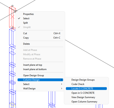
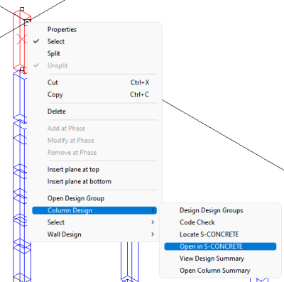
Right-click the column to bring up the right-click menu shown below and choose Column Design>Locate S-Concrete.
Click on image to enlarge.
-
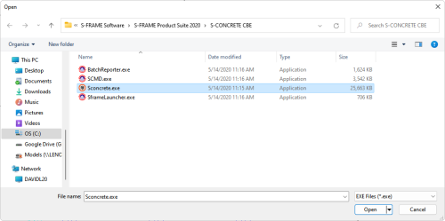
A dialog window will open where the user will navigate to the location of the Sconcrete.exe on their machine.
Click on image to enlarge.
-
Once the Sconcrete.exe file has been located, left-click on the .exe file and click the Open button of the dialog window.
-
The dialog window will close and the program's should now be linked. We can test if the two are linked by right-clicking on the column segment we assigned a Section Type to and choosing Column Design>Open in S-Concrete.
Click on image to enlarge.
-
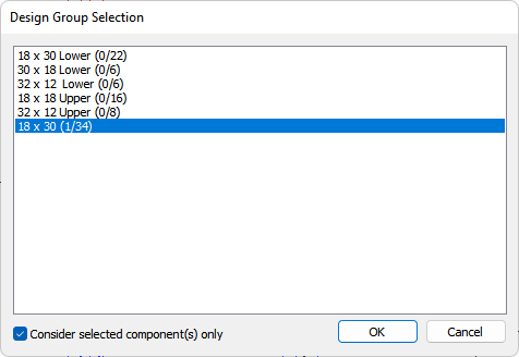
The Design Group Selection dialog will open with the section type selected that the column that was selected belongs to.
Click on image to enlarge.
-
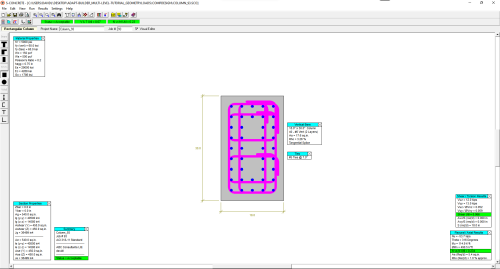
Click the OK button to open the column within S-Concrete.
Click on image to enlarge.
When using S-Concrete as the column design engine there are differences in the options of the Type-Manager, and Design Options windows. Please expand the corresponding topic below to see a list of the new settings along with a description of each. For instructions on how to use these tools refer back to the main topic for each window. Click on the link at the end of the section to go to the main topic.
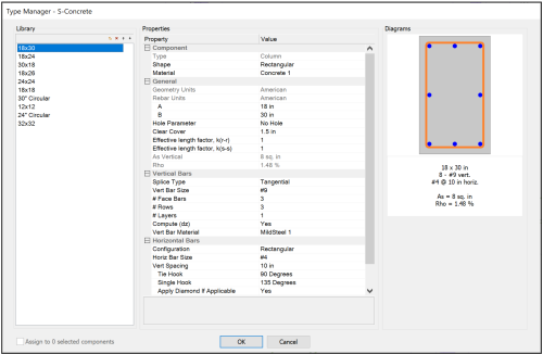
 Type Manager
Click on image to enlarge.
Click the + sign below to expand a table with a list of the Section Type properties available when using ADAPT-Builder in conjunction with S-Concrete.
 S-Concrete - Section Type Properties:
| Component
|
|
Click image to enlarge
|
-
Type - Defines the component type (Column or Beam) of the Section Type.
-
Shape - Defines the shape (Rectangular, Square, Circular, or Generic) of the Section Type.
-
Material - Defines the concrete material of the Section Type.
|
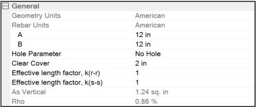
| General
|
|
|
Click image to enlarge
|
-
Geometry Units - Defines the units used to specify the geometry of the Section Type.
-
Rebar Units - Defines the units used to specify the reinforcement of the Section Type.
-
A - Defines the dimension of the Section Type in the local r-axis dimension.
-
B - Defines the dimension of the Section Type in the local s-axis dimension. B dimension only applicable to Section Types with a rectangular shape.
-
Hole Parameter - Defines if there is a hole in the column section. Use the drop down menu to choose a hole shape and define the dimensions.
-
Clear Cover - Defines the concrete cover to the tie or link measured from the outermost perimeter of the section.
-
Effective length factor, k(r-r) - column buckling about the member's local r-axis. For more information on the use of the k factor within S-Concrete refer to S-Concrete's help file.
-
Effective length factor, k(s-s) - column buckling about the member's local s-axis. For more information on the use of the k factor within S-Concrete refer to S-Concrete's help file.
-
As Vertical - Displays the total area of vertical reinforcement in the Section Type. Not editable.
-
Rho - Displays the calculated reinforcement ratio for the Section Type. Not editable.
|
|
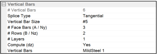
Vertical Bars
|
|
|
Click image to enlarge
|
- # Vertical Bars - Displays the calculated number of vertical bars based on user defined properties later in this section.
-
Splice Type - Defines the type of reinforcement splice (Tangential, Radial, Bearing, or Mechanical) to develop the reinforcement at the end of the column.
-
Vertical Bar Size - Defines the bar size to use for the vertical reinforcement in the Section Type.
-
# Face Bars (A / Ny) - Defines the number of bars along the A face (face along the local r-axis) of the Section Type.
-
# Rows (B / Nz) - Defines the number of rows of bars along the B face (face along the local s-axis) of the Section Type.
-
# Layers - Number of layers of vertical bars in the Section Type.
-
Compute (dz) - If set to Yes, clear distance between layers is automatically calculated.
-
Vertical Bars - Defines the material to be used for the vertical reinforcement.
|
|
Horizontal Bars
|
|
|
Click image to enlarge
|
- Configuration - Defines the general configuration of the horizontal reinforcement.
-
Tie Bar Size - Defines the size of reinforcement to be used for the horizontal ties.
-
Tie Spacing - Defines the centerline spacing of horizontal ties along the column length.
-
Tie Hook - Defines the hook type to be used for closed horizontal ties.
-
Single Hook - Defines the hook type to be used for single horizontal ties.
-
Apply Diamond if Applicable - If set to yes, the program applies diamond horizontal ties.
-
Horizontal Bars - Defines the material to be used for the horizontal reinforcement.
|
Refer to the Type Manager topic for more information on creating and assigning section types.
 Design Settings:
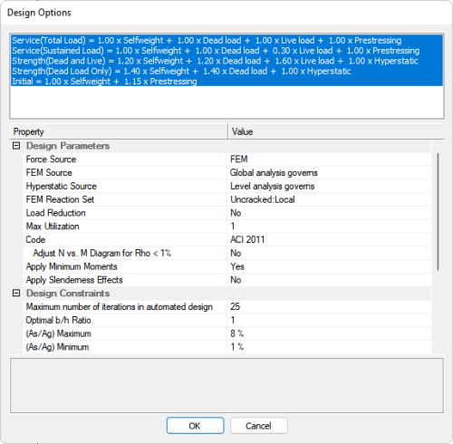
Click on image to enlarge.
Click the + sign below to expand a table with a list of the Design Option Settings available when using ADAPT-Builder in conjunction with S-Concrete.
 S-Concrete - Design Options:
| Design Parameters |
| Force Source |
Allows the user to define the source from which loading will be extracted to design
column elements.
The options are:
|
FEM
|
Utilize the most recently run Finite Element global solution reactions.
|
|
Tributary Method (Axial Gravity Only)
|
Utilize the most recent calculation using tributary gravity axial loading. Note: You must have load takedown tributaries created in the model. Generate load takedown tributaries through the Loading>Load Takedown icon.
|
|
Envelope of FEM and Tributary
|
The program will take a strict maximum envelope of axial loads and moments from the FEM and Tributary methods.
|
|
FEM Moments and larger of Tributary/FEM Axial
|
The program will use moments from the FEM analysis and the larger axial load component from either Tributary or FEM analysis. This feature could be used to exclude minimum moments from use in the design.
|
|
|
FEM Source
|
Allows the user to choose the most recently run Finite Element multi-level (Global) or single-level (Level) solution
reactions to design
column elements. Not available when the Force Source is set to Tributary Method (Axial Gravity Only).
|
|
Hyperstatic Source
|
Allows the user to choose the most recently run Finite Element multi-level (Global) or single-level (Level) solution hyperstatic
reaction to design
column elements. Not available when the Force Source is set to Tributary Method (Axial Gravity Only).
|
|
FEM Reaction Set
|
Displays the last run analysis and usage case that will be used for the FEM reactions. The format is Usage Case:Analysis Mode. The analysis mode can be local (single-level) or global (multi-level).
|
|
Load Reduction
|
Allows the user to account or not account for live load reduction in the column design. Select Yes or No to include or exclude load reduction factors from the design of columns. Yes will apply the load reductions factors. See the Live Load Reduction Factors topic for more information.
|
|
Max. Utilization
|
The maximum design utilization the program will use for column design, 1.0 being default.
|
|
Code
|
Select the appropriate design code from the drop down list. Each code may trigger an extra option, as indicated below.
|
ACI-318 & UBC
|
|
Adjust N vs. M Diagram for Rho < 1%
|
Select Yes or No
|
|
BS 8110 & CP 65
|
|
Nu (max)
|
CI 3.8.4.3 or CI 3.8.4.4
|
|
CSA 1994 & CSA 2014
|
|
Adjust N vs M Diagram for Rho < 1%
|
Yes or No
|
|
CSA 2004
|
|
Seismic Options
|
Select From:
|
No Additional Checks
|
No additional checks are made.
|
|
Clauses 21.4.4 and 21.4.5
|
Section Location and Region: Select either Face of Joint (plastic hinge region) or Away from Joint (no plastic hinge)
|
|
CIauses 21.7.2.2.3 and 21.7.2.2.4 and 21.7.2.2.5
|
Section Location and Region: Select either Face of Joint (plastic hinge region) or Away from Joint (no plastic hinge)
|
|
Clauses 21.7.2.2.3 and 21.7.2.2.4 only
|
Section Location and Region: Select either Face of Joint (plastic hinge region) or Away from Joint (no plastic hinge)
|
|
Clauses 21.12.2.6(a) and 21.12.2.6(c)
|
Theta ID (r-r): input value (default = 0.004)
Theta ID (s-s): input value (default = 0.004)
Lw (r-r): input value (default = 240in)
Lw (s-s): input value (default = 240in)
|
|
|
Adjust N vs M Diagram for Rho < 1%
|
Yes or No
|
|
EC2
|
|
Calculate Theta
|
Yes or No; If No, enter Theta (deg)
|
|
Maximum Acceptable Utilization of Concrete Without Minimum Shear/Torsion Reinforcement
|
Input value (default = 0.05)
|
|
Apply Reduced Maximum Link Spacing Requirement:
|
Yes or No
|
|
|
Apply Minimum Moments
|
The program will compute the minimum moments according to the specified building code/standard and apply it in the direction of the applied moment, if required.
|
|
Apply Slenderness Effect
|
Select Yes or No. If Yes and you are using S-Concrete as the column design module, enter BetaD.
Note: Slenderness Effect should not be applied if designing the columns using P-Delta.
|
|
|
Beta D
|
Length ratio factor (default = 0.6).
|
|
Design Constraints
|
|
Maximum number of iterations in automated design
|
Allows the user to define the number of iterations the programs will go through in solving for an acceptable design.
|
|
Optimal b/h Ratio
|
If the user wishes to maintain a certain aspect ratio of column dimension for automated/optimized design (i.e. Freeze options described below set to No).
|
|
(As/Ag) Maximum
|
Define the upper limit for reinforcement percentage Rho for automated design.
|
|
(As/Ag) Minimum
|
Define the lower limit for reinforcement percentage Rho for automated design.
|
|
Increments for Tie Spacing (+/-)
|
The program will increase or decrease the tie spacing using the basis of the entered value here. If the default value of 1” remains, then spacing may go from 6” to 7”. For example: If a value of 0.5” is used here, spacing will go from 6” to 6.5” to 7”.
|
|
Increments for Spiral Pitch (+/-)
|
Similar to option above. Default value is 0.5”
|
|
Increments for Hole Dimensions (+/-)
|
If a column Design Section includes a hole within its cross section, the automated design of the program can increase or decrease the size of this hole in increments specified in this field.
|
|
Freeze Dimension A
|
Yes or No. Selecting Yes will force the dimension to be kept as specified in the Design Section definition, for instance in the case when checking the capacity of an existing building design that has already been built, or if column sections can no longer change size. If No, three rows of options will appear
|
|
|
Dimension A Maximum
|
Enter maximum dimension, which the column cannot be any larger than, in the specified direction
|
|
|
Dimension A Minimum
|
Enter the minimum dimension, which the column cannot be any smaller than, in the specified direction
|
|
|
Dimension A Increments (+/-)
|
Specify the increments with which the column size will be increased or decreased.
|
|
Freeze Dimension B
|
Yes or No. Selecting Yes will force the dimension to be kept as specified in the Design Section definition, for instance in the case when checking the capacity of an existing building design that has already been built, or if column sections can no longer change size. If No, three rows of options will appear
|
|
|
Dimension B Maximum
|
Enter maximum dimension, which the column cannot be any larger than, in the specified direction
|
|
|
Dimension B Minimum
|
Enter the minimum dimension, which the column cannot be any smaller than, in the specified direction
|
|
|
Dimension B Increments (+/-)
|
Specify the increments with which the column size will be increased or decreased.
|
|
Freeze Horizontal Bar Size
|
Yes or No. If Yes, bar size will not be changed in automated design. If No, the user can define maximum and minimum size increase and reduction that the program would use in automated design.
|
|
|
Increase bar size by max.
|
Enter the number of bar sizes the program is allowed to increase the specified bar size by when designing the columns.
|
|
|
Reduce bar size by max.
|
Enter the number of bar sizes the program is allowed to reduce the specified bar size by when designing the columns.
|
|
Freeze Vertical Bar Size
|
Yes or No. If Yes, bar size will not be changed in automated design. If No, the user can define maximum and minimum size increase and reduction that the program would use in automated design.
|
|
|
Increase bar size by max.
|
Enter the number of bar sizes the program is allowed to increase the specified bar size by when designing the columns.
|
|
|
Reduce bar size by max.
|
Enter the number of bar sizes the program is allowed to reduce the specified bar size by when designing the columns.
|
|
Freeze Spice Type
|
Yes or No. If No, the program may suggest an alternate splice type than.
|
Refer to the Design Options topic for more information on the Design Options window..
S-Concrete Specific Parameters
Below are a list of inputs specific to S-Concrete for use with moment magnification allowed by older ACI codes.
K Factor (Effective Length Factor):
The K Factor is also referred to as the effective length factor. k(r-r) is for column buckling about the member's local r-axis and k(s-s) is used for column buckling about the member's local s-axis.
If the default K Factor value of 1 is changed, that value will be used for the entire length of the physical member. The K Factor is defined per section type within the Type Manager panel.
Unbraced Length:
ADAPT-Builder automatically calculates the unbraced length of a column as the member's unsupported length. This value can be overridden by the user in the Properties Grid > Unbraced Length when a column or multiple columns are selected..
The Lu values, Lu (s-s) and Lu (r-r), represent the unbraced length of column members with respect to column type buckling about the member's local s and r axes, respectively. See S-Concrete help menu for the use of Unbraced Lengths in S-Concrete.
Cm Coefficients (Interactive Bending Coefficient):
The Cm Coefficients are used to check the column for Euler buckling, and for the Moment Magnification Procedure in older editions of the ACI code. Cm(r-r) is for bending about the column's local r axis and Cm(s-s) is for bending about the column's local s axis.
In the ACI design code, the Cm values are only applicable for non-sway frames.
Code Check
ADAPT-Builder in conjunction with S-Concrete includes the ability to perform a code check of individual columns. During the code check S-Concrete will use the Section Type for that column, and compare them to the loads which each column will resist in its location of the structure. The program will return code check results deeming the column as passing code specifications (OK) or not (NG). The S-Concrete - Code Check can be executed from the Section Type Selection window that opens when a user clicks the Solve button to execute the column design. Once the code check is complete, if columns are failing or not optimized the user can choose to use the S-Concrete - Design feature to have S-Concrete find a suitable design for the column within the constraints set by the user. Additionally the user can consider P-Delta effects in the code check or design of columns. Click the + sign below to expand instructions on how to perform a S-Concrete - Code Check.
 To perform a S-Concrete code check:
-
Assign Columns to a Section Type.
-
Assign Column Labels.
-
Define P-Delta Load Combinations. (if applicable)
-
Review and modify Unbraced Lengths. (if applicable)
-
Review and modify the K factor for each section type. (if applicable)
-
Perform a Single-Level or Multi-Level Analysis and/or generate Tributary Loads.
Note: The FEM column reactions used in the code check of columns will be based on the Force Source and Hyperstatic Source settings of the Column Design Settings window.
-
Set the Column Design Settings to use for your design.
-
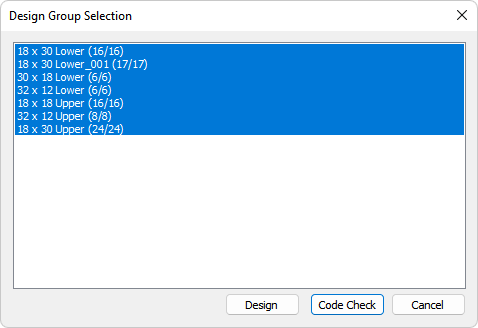
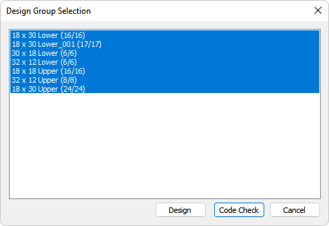
Go to Column Design>Design and click on the Solve icon to open the Design Group Selection window.
-
Select the Section Types you want to design. Alternatively, you can window select the column segments you want to design prior to clicking the Solve icon to selectively code check the selected columns.
-
Click the Code Check button to start the process of checking the columns code compliance. When completed the program will prompt you that the process is complete. During the execution of the Code Check the program will display a status bar.

-
Once the Code Check is complete the status bar will disappear and you will regain control of the software. You can then view the Graphical Code Check Results or a Column Design Summary. Where a column fails the code check the user can use the S-Concrete - Design feature, to have S-Concrete design the column within the constraints set by the user.
Code Check Results
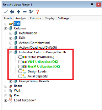
After the user has executed a column code check the user can view the graphical results through the Results View panel. The applicable results to a column code check are found in the Column>Individual Column Design Results tree as shown below.
Click on image to enlarge.
The user can check the overall column status, the V&T Utilization, NvsM Utilization, Design Loads, and/or Axial Capacity result.
Note: The results in the Design Group Results tree are applicable to a column Design and not a column Code Check. Column Code Check results are only available through the Individual Column Design Results tree. After accepting a change in section type from a column design with S-Concrete the user must run the code check again for the individual column design results to be updated with the results from the column design.
Click the + sign below to expand instruction on how to view graphical S-Concrete code check results.
 To view a graphical result:
-
Perform a Code Check for the section types you want to code check.
-
Go to Column Design ribbon and click on the Columns Only.png) icon to show only the columns within the model. This allows for easier viewing of the column code check results.
icon to show only the columns within the model. This allows for easier viewing of the column code check results.
-
Move to an isometric view of the model by clicking on the Top-Front-Right View icon of the Bottom Quick Access Toolbar.
-
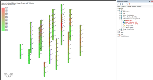
In the Results View panel select the result you want to view from within the Column>Individual Column Design Results tree. In the example below we are viewing the V&T Utilization. The status of this result is indicated in the result tree (OK or NG).
-
The results will become visible on screen. A legend for the result will appear in the upper right of the model space.
Click on image to enlarge.
-
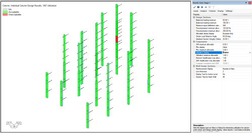
To change the display of results from their value to display the Pass/Fail status, select the Display tab of Results View panel and change the Utilization to Statusas shown in the image below.
Click on image to enlarge.
-
The user can check other results in the Column>Individual Column Design Results tree in a similar fashion.
Column Design
ADAPT-Builder in conjunction with S-Concrete includes the ability to perform a design of the columns located within the Section Type. The user has the ability to set the design constraints in the design settings to design by. S-Concrete will propose a working design for the column if one can be found given the constraints. The user can then accept the design and apply it to the section types in the model. The effects of P-Delta can also be included in the column design process. Click the + sign below to expand instruction on how to perform a S-Concrete - Column Design.
 To perform a S-Concrete column design:
-
Assign columns to a Section Type.
-
Assign Column Labels.
-
Define P-Delta Load Combinations (if applicable)
-
Review and modify the Unbraced Lengths. (if applicable).
-
Review and modify the K factor for each section type. (if applicable)
-
Perform a Single-Level or Multi-Level Analysis and/or generate Tributary Loads.
Note: The FEM column reactions used in the code check of columns will be based on the Force Source and Hyperstatic Source settings of the Column Design Settings window.
-
Set the Design Settings & Constraints in the Design Settings dialog.
-
Run a Single-Level or Multi-Level Analysis.
-
Go to Column Design>Design and click on the Solve icon to open the Design Group Selection window.
Click on image to enlarge.
-
Select the Section Types you want to design. Alternatively, you can window select the column segments you want to design prior to clicking the Solve icon to selectively code check the selected columns.
-
Click the Design button to start the process of designing the columns to be code compliant. When completed the program will prompt you that the process is complete. During the column design process the program will display a status bar.
Click on image to enlarge.
-
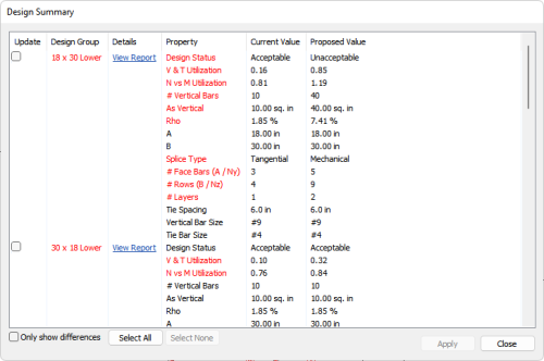
Once the design is complete a Design Summary window will open.
Click on image to enlarge.
-
The user can review the Proposed Value column to see the results of the design process. Once the user has reviewed the results the user can accept the changes and apply them to the section types. Check the box under the update column for the section types you want to accept the proposed design for and click the Apply button. Alternatively, the user can close the Design Summary window without accepting any changes by clicking on the Close button without selecting any update check box.
Note: If changes to the section type are accepted and you have previously run a code check using S-Concrete, the code check results within the Individual Column Design Results tree are no longer valid. You must run the code check after accepting the changes from the column design to update the results in the Individual Column Design Results tree.
-
Once the updates to the section types are applied the user can view the Design Group Results.
Design Group Results
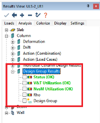
After a column design has been executed the graphical results can be viewed through the Results View panel. The applicable results to a S-Concrete column design are found in the Column>Design Group Results tree as shown below. The user can check the overall column status, the V&T Utilization, NvsM Utilization, Design Loads, Rho, and/or Axial Capacity result.
Click on image to enlarge.
Note: The results in the Design Group Results are applicable to a column Design and not a column Code Check. Column Code Check results are only available through the Individual Column Design Results tree. After accepting a change in section type from a column design with S-Concrete the user must run the Code Check again for the Individual Column Design results to be updated with the results from the Column Design.
Click the + sign below to expand instructions on how to view graphical design group results.
 To view a graphical design group results:
-
Perform a S-Concrete Column Design for the section types (design groups) you want to design.
-
Go to Column Design ribbon and click on the Columns Only.png) icon to show only the columns within the model. This allows for easier viewing of the column code check results.
icon to show only the columns within the model. This allows for easier viewing of the column code check results.
-
Move to an isometric view of the model by clicking on the Top-Front-Right View  icon of the Bottom Quick Access Toolbar.
-
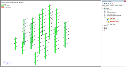
In the Results View panel select the result you want to view from within the Column>Design Group Results tree. In the example below we are viewing the V&T Utilization. The status of this result is indicated in the result tree (OK or NG).
-
The results will become visible on screen. A legend for the result will appear in the upper left of the model space.
Click on image to enlarge.
-
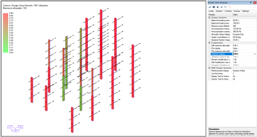
To change the display of results from Pass/Fail mode to display the value, select the Display tab of Results View panel and change the Utilization to Value.
Click on image to enlarge.
-
The user can check other results in the Column>Design Group Results tree in a similar fashion.
P-Delta
Using S-Concrete the user can account for slenderness effects using one of two methods. The user can code.check or design the columns considering slenderness effects using 2nd order (P-Delta) analysis of ADAPT-Builder or choose to have S-Concrete perform moment magnification to consider the slenderness effects.
 To consider slenderness effects using P-Delta:
-
Assign columns to a Section Type.
-
Assign Column Labels.
-
Define P-Delta Load Combinations
-
Perform a Single-Level or Multi-Level Analysis and/or generate Tributary Loads..
Note: The FEM column reactions used in the code check of columns will be based on the Force Source and Hyperstatic Source settings of the Column Design Settings window.
-
Set the Design Settings & Constraints in the Design Settings dialog.
-
In the Design Settings dialog make sure to set the Apply Slenderness Effects to NO.
Note: When designing with ADAPT-Builder P-DELTA load combinations the effects of slenderness are accounted for already.
-
Go to Column Design>Design and click on the Solve icon to open the Design Group Selection window.
Click on image to enlarge.
-
Select the Section Types you want to design. Alternatively, you can window select the column segments you want to design prior to clicking the Solve icon to selectively code check the selected columns.
-
Click the Design button to start the process of designing the columns to be code compliant. When completed the program will prompt you that the process is complete. During the column design process the program will display a status bar.
Click on image to enlarge.
-
Once the design is complete a Design Summary window will open.
Click on image to enlarge.
-
The user can review the Proposed Value column to see the results of the design process. Once the user has reviewed the results the user can accept the changes and apply them to the section types (design groups). Check the box under the update column for the section types (design groups) you want to accept the proposed design for and click the Apply button. Alternatively, the user can close the Design Summary window without accepting any changes by clicking on the Close button without selecting any update check box.
Note: If changes to the section type (design group) are accepted and you have previously run a code check using S-Concrete, the code check results within the Individual Column Design Results tree are no longer valid. You must run the code check after accepting the changes from the column design to update the results in the Individual Column Design Results tree.
-
Once the updates to the section type (design groups) are applied the user can view the Design Group Results.
 To consider slenderness effects using S-Concrete moment magnification:
-
Assign columns to a Section Type.
-
Assign Column Labels.
-
Check and revise Unbraced Lengths as necessary.
-
Perform a Single-Level or Multi-Level Analysis.
Note: The FEM column reactions used in the code check of columns will be based on the Force Source and Hyperstatic Source settings of the Column Design Settings window.
-
Set the Design Settings & Constraints in the Design Settings dialog.
-
In the Design Settings dialog make sure to set the Apply Slenderness Effects to YES.
Note: When designing using S-Concrete without P-DELTA load combinations the user must choose to include the effects of slenderness for them to be accounted for. S-Concrete will check the slenderness of the column and perform moment magnification to design the column appropriately. See the S-Concrete help menu for more information.
-
Go to Column Design>Design and click on the Solve icon to open the Design Group Selection window.
Click on image to enlarge.
-
Select the Section Types you want to design. Alternatively, you can window select the column segments you want to design prior to clicking the Solve icon to selectively code check the selected columns.
-
Click the Design button to start the process of designing the columns to be code compliant. When completed the program will prompt you that the process is complete. During the column design process the program will display a status bar.
Click on image to enlarge.
-
Once the design is complete a Design Summary window will open.
Click on image to enlarge.
-
The user can review the Proposed Value column to see the results of the design process. Once the user has reviewed the results the user can accept the changes and apply them to the section types (design groups). Check the box under the update column for the section types (design groups) you want to accept the proposed design for and click the Apply button. Alternatively, the user can close the Design Summary window without accepting any changes by clicking on the Close button without selecting any update check box.
Note: If changes to the section type (design group) are accepted and you have previously run a code check using S-Concrete, the code check results within the Individual Column Design Results tree are no longer valid. You must run the code check after accepting the changes from the column design to update the results in the Individual Column Design Results tree.
-
Once the updates to the section types (design groups) are applied the user can view the Design Group Results.
S-Concrete Summary Report
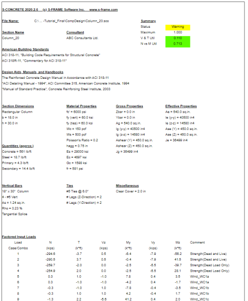
In addition to the graphical code check or design group results the user can see a Column Design Summary HTML report for the column after performing an S-Concrete - Code Check or Design. Click the + sign below to expand instructions on creating the design summary reprot of a column.
 To open the design summary report:
-
Perform a S-Concrete Code Check or a S-Concrete - Column Design for the section types (design groups) you want to code check.
-
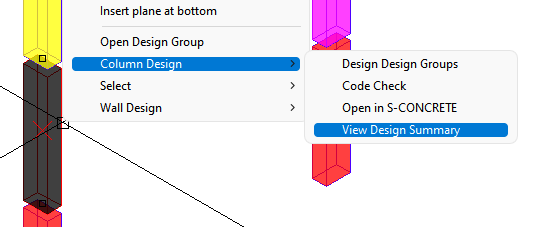
When the procedure is complete right-click a column segment you would like to see the design summary for and choose Column Design>View Design Summary from the right-click menu.
-
An HTML report will open in your web browser showing the design summary for the column similar to that shown below.



 icon to open the Design Group Selection window.

.png) icon to show only the columns within the model. This allows for easier viewing of the column code check results.
icon to show only the columns within the model. This allows for easier viewing of the column code check results. 