This section summarizes the design code requirements and design procedure of regular and special shear walls based on ACI 318-2011 and the algorithms used for ADAPT Wall Designer (AWD).
As a minimum, a special structural wall must contain distributed web (panel) reinforcement in both horizontal and vertical directions. A special structural wall also includes vertical reinforcement concentrated at the wall boundaries to provide additional resistance to moment and axial force. Longitudinal reinforcement is enclosed in transverse reinforcement to confine the concrete and restrain longitudinal rebar buckling.
A boundary element is a portion of a structural wall edge or opening that is strengthened by both longitudinal and transverse reinforcement. Where combined seismic and gravity loading results in high compressive demands on the edge, ACI 318 requires usage of a special boundary element. These elements incorporate closely spaced transverse reinforcement enclosing the vertical boundary bars, increasing compressive strain capacity of core concrete and restraining longitudinal rebar buckling.
Minimum Reinforcement
The provision ACI 318 section 16.4.2 defines minimum amounts of vertical and horizontal reinforcement for the walls.
Regular Structural Walls
Calculation of minimum distributed web reinforcement is governed by ACI 318-11 section 11.4.6.3, and ACI 318-11 section 14.3.3.
Minimum vertical reinforcement is also governed by ACI 318-11 section 14.3.2:
Special Structural Walls
Calculation of minimum distributed web reinforcement is also governed by ACI 318-11 section 21.9.2.1. The distributed web reinforcement ratios, ρl for vertical reinforcement and ρt for horizontal reinforcement, must be at least 0.0025, except that ρl and ρt are permitted to be reduced if Vu ≤ Acvλ√f’c . Reinforcement spacing each way is not to exceed 18 inches. At least two curtains (layers) of reinforcement are required if Vu > 2Acvλ√f’c .
Wall Shear Strength Design
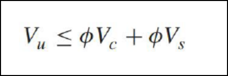
The design shear strength of a wall is equal the sum of concrete shear strength plus the reinforcement shear strength as follows:
Click on image to enlarge.
The nominal shear strength of any section of the wall cannot exceed the requirements of ACI 318-11 section 11.9.3 & 11.9.4.
The value of shear strength provided by concrete Vc cannot exceed the requirements of ACI 318-11 section 11.2.1.1:
If demand shear Vu exceeds ɸVc, design of shear reinforcement for walls is governed by requirements of ACI 318-11, section 11.9.9.
The calculation of shear web reinforcement is performed according to ACI 318-11 section 11.4.7.2 or by similar requirement of section 11.9.9.1.
The spacing of vertical shear reinforcement is governed by section 11.9.9.5.
Wall P-M Strength Design
The strength calculations for structural walls resisting combined flexure and axial force directly are similar to the calculations for concrete columns in accordance with requirements of ACI 318-11 chapter 10.
Specifically, the calculations assume linear strain distribution, idealized stress-strain relations for concrete and reinforcement, and material strain limits per ACI 318 § 10.2 and 10.3. Boundary elements and the wall web are considered effective. Portion of vertical shear rebars which is more than required is included in moment calculations with equal spaces.
For combined flexure and axial force in a wall, the strength reduction factor φ is determined based on ACI 318-11 section 9.3.2.
For this purpose, et is defined as the net tensile strain in the extreme tension steel when the section reaches nominal strength (ecu = 0.003). If et ≥ 0.005, φ = 0.9. If et ≤ fy (taken as 0.002 for Grade 60), φ = 0.65 for tied boundary elements or 0.75 for spiral reinforced boundary elements. The value of φ is interpolated for intermediate values of et.
The maximum nominal compression force strength is given by ACI 318-11 section 10.3.6.
The maximum nominal tension force that the wall can carry is given by ACI 318-11
Pot = fyAs
The program uses the requirements of strain compatibility to determine the nominal axial strength and moment strength (Pn, Mn) of the wall pier. The coordinates of these points are determined by rotating linear strain line on the section of the wall pier. the maximum concrete strain is always taken as −0.003 and the maximum steel strain is varied from −0.003 to plus infinity. When the steel strain is −0.003, the maximum compressive force in the wall pier, Poc, is obtained from the strain compatibility analysis.
When the steel strain is plus infinity, the maximum tensile force in the wall pier, Pot, is obtained.
The compressive stress in the concrete is calculated (ACI 10.2.7.1) as follows:
0.85f'cβ1 ctp
The value of β1 is determined from ACI 318-11 section 10.2.7.3.
The computer algorithm implemented in ADAPT Wall Designer considers loading cases, where either left or right side of the wall is in compression.
Special Boundary Elements
ACI 318 provides two methods for determining whether special boundary elements are required.
Strain Method:
The preferred method is the strain method (Method "Strain > 0.003") (ACI 318 section 21.9.6.2). The method applies to walls that are effectively continuous from base of the structure to top of wall or segment and designed to have a single critical section for flexure and axial force.
To use this method, the seismic force-resisting system is first sized and then analyzed to determine the top-level design displacement du and corresponding maximum value of wall axial force Pu. The flexural compression depth c corresponding to nominal moment strength Mn,CS under axial force Pu is then calculated. If the compression zone exceeds ACI 318-11 Eq. 21-8.
Where hw refers to total wall height from critical section to top of wall, then special boundary elements are required. Where special boundary elements are required by Method I, they must extend vertically above and below the critical section a distance not less than the greater of lw and Mu,CS/4Vu,CS.
Stress Method:
The second method (Method "Stress > 0.2 f'c") for determining if special boundary elements are required, is based on nominal compressive stress (ACI 318 section 21.9.6.3).
First, the seismic force-resisting system is sized and analyzed to determine axial forces and moments under design load combinations. Using a gross-section model of the wall cross section, nominal stress at wall edges is calculated from s = Pu/Ag + Mux/Sgx + Muy/Sgy. Special boundary elements are required at an edge if nominal stress exceeds 0.2f’c. If a special boundary element is required, it must be continued vertically (upward and downward) until compressive stress drops below 0.15f’c. Method "Stress > 0.2 fc" can be used for any wall. The preferred use is for irregular or discontinuous walls for which Method "Strain > 0.003" does not apply.
Where a special boundary element is required, ACI 318 section 21.9.6.4 (a) requires it to extend horizontally from the wall edge a distance not less than the greater of c – 0.1lw an c/2. Flexural compression depth c is calculated at nominal moment strength Mn,CS under maximum axial force Pu.
Special boundary elements must have transverse confinement reinforcement satisfying requirements of ACI 318-11 section 21.6.4.4(b) & 7.10.5.1:
Spacing of transverse reinforcement shall satisfy requirements of ACI 318-11 section 21.9.6.2-4:
At wall boundaries where special boundary elements are not required, ACI 318 section 21.9.6.5 requires usage of ordinary boundary elements if the boundary element longitudinal reinforcement ratio As,be/Ag,be > 400/fy, where As,be/Ag,be is the local ratio at the wall boundary only.
Where As,be/Ag,be ≤ 400/fy, ACI 318 section 21.9.6.5 permits the section to be detailed without ties enclosing the vertical reinforcement.
At the interface with a footing, foundation mat, pile cap, or other support, longitudinal reinforcement of structural walls must be fully developed in tension. Development length "Ld" for vertical bars of special element anchored in footing is calculated based on ACI 318-11 section 21.2.3 & 12.2.3.
Development length "Ldh" for horizontal web bars anchored in special elements is calculated according to ACI 318-11 section 21.9.2.3 & 12.5.2.
Wall Slenderness Checks
The algorithm implemented in ADAPT Wall Designer calculates the slenderness ratio of the wall as follows:
lu / r
where:
lu - clear story height
r - radius of gyration of the wall
Slenderness ratio is checked against the limiting condition:
lu / r ≤ 34
which is equivalent to the ACI 318-11 Section 10.10.1 Eq 10-7 requirement.
The calculation of radius of gyration of a wall is done using simplified formula:
r=0.29*min (t , Lw)
Thin wall sections responding in flexure may be prone to out-of-plane buckling, typically at higher ductility levels. The 1997 UBC code Section 1921.6.6.6 prescribes a minimum wall thickness of 1/16 the clear story height for walls that require boundary confinement.
The algorithm implemented in ADAPT Wall Designer checks the condition:
lu / 16 ≤ t
where:
t - wall thickness
lu - the length which is an input parameter, should be is taken as the smaller of:
-
The clear story height between floors bracing the wall in the out-of-plane direction.
-
2.5lp for single-curtain walls and walls with ρ greater than 200 / fye, or 2.0lp for two-curtain walls with ρ less than or equal to 200 / fye.
-
ρ = Local reinforcement ratio in boundary region of wall.
Wall Zone-less Design
The designs (investigation and auto-design) of ordinary walls can be performed in two possible modes:
Zone-less design is controlled by a switch "ZoneLessDesign". This mode of operation is pertaining only to ordinary walls without special boundary elements. If special zones are selected, the zone-less design selection will be ignored.
If zone-less mode is selected, the program will ignore the input pertaining to the flexural zone rebar, and assume that the number of zone bars ("BarCount_Left", "BarCount_Right") is equal zero. In such case, the program will check or design the walls flexural capacity (P-M Interaction check) assuming that the panel vertical shear rebar are distributed over the entire length of the wall and it fully participates in flexural capacity.
The input parameters (AWL file) for such models should be set as follows:
"ZoneLessDesign" 1
"BarCount_Left" 0
"BarCount_Right" 0
In the case where the program is run in investigation (calculate) mode the capacity of the wall based on the assumed panel rebars will be code-checked.
In case program is run in auto-design mode, the design for shear will be followed for iterative design for flexure, where the amount of panel rebar and bar sizes will be increased to satisfy the flexural demand. If program is unable to satisfy the requirements for flexural capacity using distributed panel reinforcement, the auto-design calculations will attempt to switch to design including zone reinforcement.
-
The operation of the auto-design algorithm including the zone-less designs can be presented by the following pseudo-code:
-
Design vertical panel rebar to satisfy the shear requirements.
-
Test if boundary zones are required/selected and if so go to (6).
-
Test if program is supposed to try to design using panel rebar only. If YES go to next step (4), if NO go to step (6).
-
Test if selected vertical panel shear rebar satisfy flexural requirements, and if so stop (exit).
-
Try to adjust vertical panel rebar (bar size spacing) to satisfy the flexural requirements (PM interaction). If satisfied stop (exit).
-
Design for flexure using the zone bars.
-
Design for boundary zones if required.
Utilization Factors
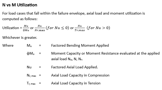
The following formula (American Standards) is used for calculation of axial and flexural utilization ratios:
Click on image to enlarge.
Axial utilization is the ratio of the ultimate applied axial load Pu divided by axial capacity of the section ɸ*Pn. Moment utilization is the ratio of ultimate applied moment Mu divided by the moment capacity ɸ*Mn evaluated at the level of applied axial load Pu. The calculations of utilization ratios for shear are performed using the following formula:
Utilization= Vu/ (ɸ*Vn), where Vn=Vc+Vs.
The program selects maximum values from each load case under consideration. The governing load case number is also reported for each of these.