ADAPT-Builder includes the ability to evaluate columns for code compliance (ACI code only). The user has the ability to assign both vertical and horizontal reinforcement to a column through the use of Section Types and choose the Design Settings to use when checking the column for code compliance. The user can then perform a Code Check to check code compliance with or without consideration of the effects of P-Delta. Where the column fails code compliance, the user can manually Optimize Columns Using Code Check to bring the column within code compliance.
The procedure to code check columns consists of the following:
Define Section Types and assign them to columns.
Edit Section Type Reinforcement as needed.
Relabel Column Stacks to have consistent labels.
Set up P-Delta Combinations (if applicable).
Set the column Design Settings to be used in the code check of columns.
Use the Solve command to perform a Code Check of the column.
In addition to the integrated ability to evaluate columns for code compliance, ADAPT-Builder integrates with S-Concrete for the evaluation of columns as well. S-Concrete is a 3rd party software and is not included with ADAPT-Builder. Please refer to the S-Concrete topic for more information.
This section describes the equations and assumptions used by ADAPT-Builder for column design. Column design can be performed for standard rectangular, square, and circular column shapes based on the selected Design Code. ADAPT-Builder will code check for axial, bending capacity, and shear capacity using the design loads and user-defined reinforcement for each column.
Columns will be checked for all of the requirements for Ordinary Moment Frames except for the additional requirements indicated in ACI 318-14 Section 18.3, which should be checked by hand. See the Code Limitations section for code requirements not met by ADAPT-Builder.
Torsion – Columns ignore torsion with respect to the design of shear reinforcement.
Creep / Long Term Deflections – No considerations are taken in the analysis to account for the effects of creep or long term deflections.
Column Design – Columns will be designed using the PCA Load Contour Method.
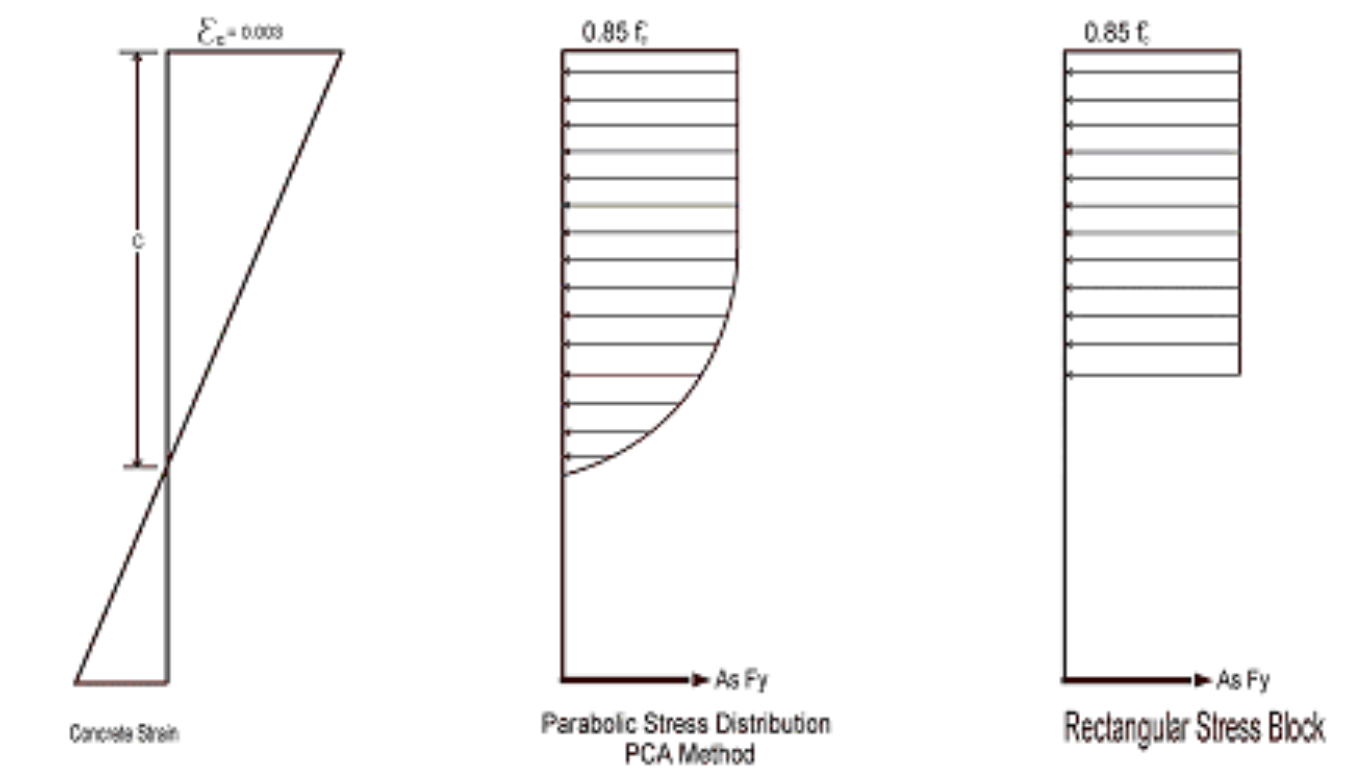
You can specify whether you want your concrete design to be performed with a rectangular stress block, or with a more accurate parabolic stress block. While most hand calculations are performed using a rectangular stress block, the parabolic stress block is more accurate. In fact, most of the PCA design aids are based upon the parabolic stress distribution. A good reference on the parabolic stress block is the PCA Notes on ACI 318-99.
Click on image to enlarge.
ADAPT-Builder uses the PCA Load Contour Method for the code check of columns. The PCA Load Contour Method is an approximation based on the uniaxial failure conditions and the Parme Beta factor. A good reference on the Load Contour Method is chapter 12 of the PCA Notes on ACI 318-99.
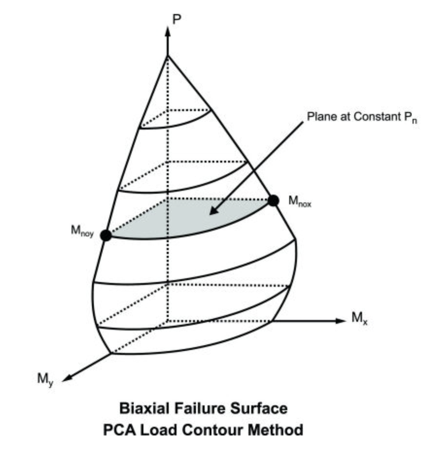
Click on image to enlarge.
Since columns are designed for biaxial bending, they require more information about the location and arrangement of the bars.
For rectangular and square columns, the vertical (bending) reinforcement layout of the column is defined by entering the number of Face and Row bars as well as the number of Layers. Face and Row bars must always be defined, each containing at least two bars. The CGS of the first and last Face or Row bars will be at a distance equal to the clear cover + the diameter of the Horizontal bar+ 1/2 the diameter of the vertical bar from each column face. Additional Face and Row bars in that layer will be placed so that they are evenly spaced in that layer. A maximum of two layers of vertical bars can be defined.
The horizontal (shear) reinforcement of the column is defined by the diameter of the horizontal bar, the number of legs, and the spacing between horizontal bar layers (z-direction). The CGS to the first and last leg are located at a distance of the Clear Cover + 1/2 the horizontal bar size from each column face. Additional legs will be equal spaced between the outer legs.
The below figure is a column with the number of Face bars set to 5 and the number of Row bars set to 4. The dashed purple bars represent a 2nd layer of Face and Row bars if the user has chosen two layers. The user can define column reinforcement through the use of Section Types.
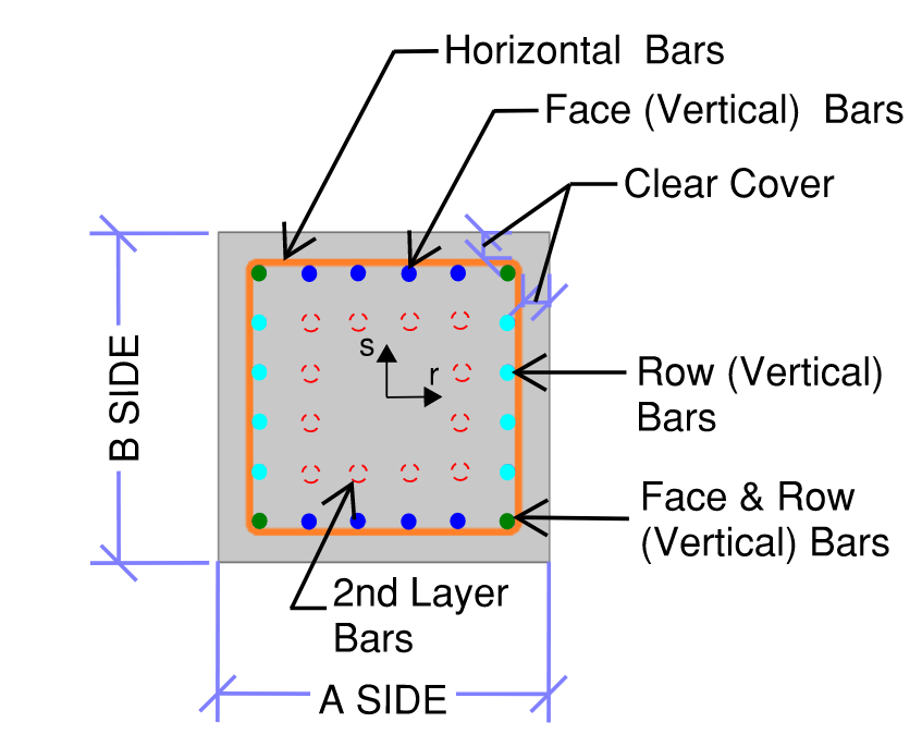
Click on image to enlarge.
For circular columns, the layout of the bars includes horizontal (shear) reinforcement defined by its diameter and spacing between horizontal bars along the length of the column. The distance from the face of column to the CG of the horizontal bars is the clear cover + 1/2 the horizontal bar diameter. Vertical (bending) reinforcement is defined by the number of bars and bar size. Vertical bars are spaced equally. The distance from the face of column to the CG of the vertical bars is the clear cover + the horizontal bar diameter + 1/2 the vertical bar diameter. The user can define column reinforcement through the use of Section Types.
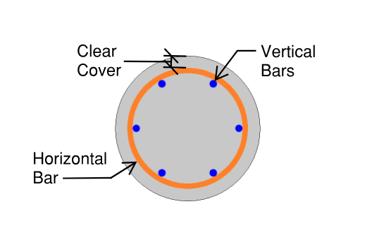
Click on image to enlarge.
Shear Design –When ACI 318-19 is selected, the shear strength of concrete (Vc) uses equations in Table 22.5.5.1. Note that for members meeting the minimum shear reinforcement requirement (Av≥Av,min), Vc is taken as the larger of the results calculated by the equations (a) and (b) in the table. ACI 318-19 code suggests ρw may be taken as the sum of the areas of longitudinal bars located more than two-thirds of the overall member depth away from the extreme compression fiber. Therefore, ADAPT-Builder calculates ρw as the sum of the areas of longitudinal bars on the tension face.
When other ACI 318 editions are selected, the shear strength of the concrete alone is limited to the standard 2*λ*sqrt (f'c) equation from ACI 318-14 Section 22.5.5.1 (ACI 318-11 Section 11.2.1.1) and does not use the more detailed calculations of ACI 318-14 Table 22.5.5.1 (ACI 318-11 Section 11.2.2). Also, note that for members with significant axial tension (greater than 0) the program designs the shear reinforcement to carry the total shear per ACI 318-14 Section R22.5.7.1 (ACI 318-11 Section 11.2.1.3).
Threshold Torsion - The program will adjust the threshold torsion value for the presence of axial force in a column.