Beam Design
Beam design within ADAPT-Builder is similar to that of slab design. Support lines are added such that the design sections cut the beam to be designed. During the design of the sections the program calculates Longitudinal and One-Way Shear reinforcement for moment capacity and minimum reinforcement provisions of the selected design code. The design of Torsion can be included as well if using ACI-2019 code. ADAPT-Builder designs combined beam and slab sections as composite sections. Beams can be designed using the full tributary width or the Effective Flange Width.
Modeling of Beams
Beams can be modeled on their own or in conjunction with a slab region. Beams are rectangular, however, a curved beam can be idealized using straight beam segments. Where a beam and a slab overlap the stiffness of the section will be increased. A wide shallow beam will have a higher stiffness increase than a thin deep beam. It is recommended to model a composite beam/slab T-section such that the slab represents the flange of the beam and the beam component represents the stem of the beam. Modeling beams in this fashion the beam component will have to be offset such that the top of the beam is located at the soffit of the slab region. Modeling in this fashion will negate any stiffness increase as the beam and slab will no longer overlap in the z-direction.
Support Lines for Beam Design
Before laying out support lines for a beam design the user must choose the option to use for the design of beams and how they are accounted for in the model.
-
Go to Criteria>Analysis/Design Options to open the design criteria to the Analysis/Design Options tab.
Click on image to enlarge it
-
In the General Analysis and Design Options section the first two options are Regular Floor Systems and Waffle/Joist Construction. The two options are described below.
-
Regular Floor Systems - Using this option the user must snap a support line vertex on at least one end of the beam in order for the beam to be accounted for within the design. If the support line is not snapped to the beam at one end and a section cuts the beam the beam will be ignored when the program idealizes the design section for design.
-
Waffle/Joist Construction = Using this option the user does not need to snap on a beam for it to be accounted for within the design. If the design section from a support line cuts a beam or multiple beams, the beam(s) will be included in the idealized section. All beams crossed by the section will be idealized to the centroid of the section.
-
Select the option you wish to use for your design.
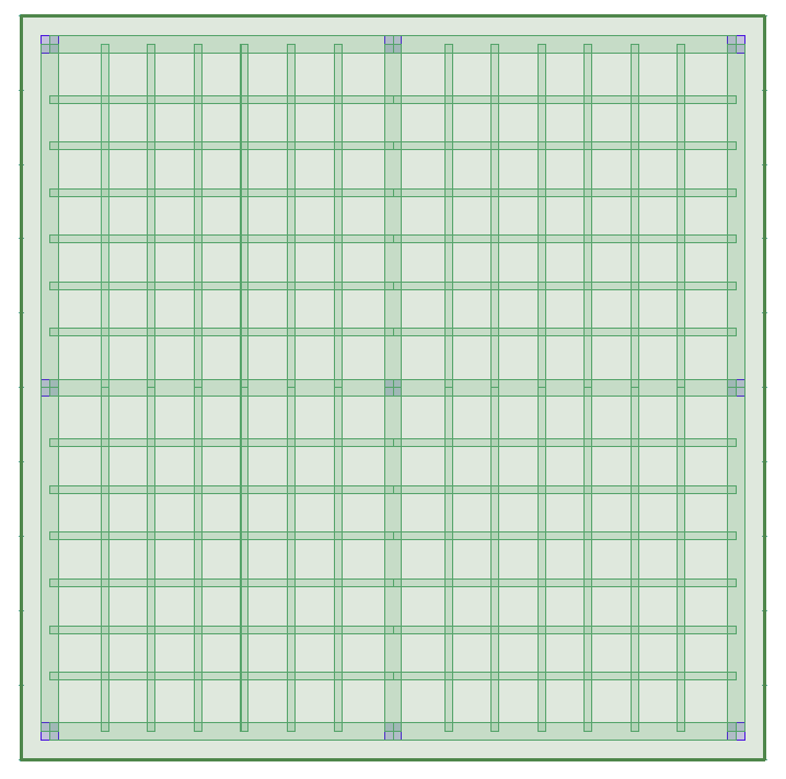
Laying out support lines for beam design is different depending on if you are designing using the Regular Floor System option or the Waffle/Joist Construction option of the design criteria. Below we will use a waffle slab with 18 inch wide girders and 8 inch wide rib beams to illustrate the difference in laying out support lines for each option. The example slab is shown below.
Click on image to enlarge it
 Layout of Support lines for Regular Floor Systems:
Using the Regular Floor System option each beam that the user would like to design must have a support line added to it. The support line must be snapped to at least one end of the beam in order for the beam stem to be considered in the design. Support lines can be added to the beam using the Dynamic Editor or Manually.
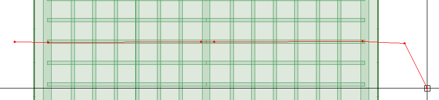
Note: When using the dynamic editor to create beam support lines you must click a construction line vertex close to each beam end within the beam. For example in the below image we have two beams in the horizontal direction. Therefore, when drawing the construction line we have clicked 4 vertices within the beams, one at each end.
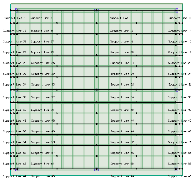
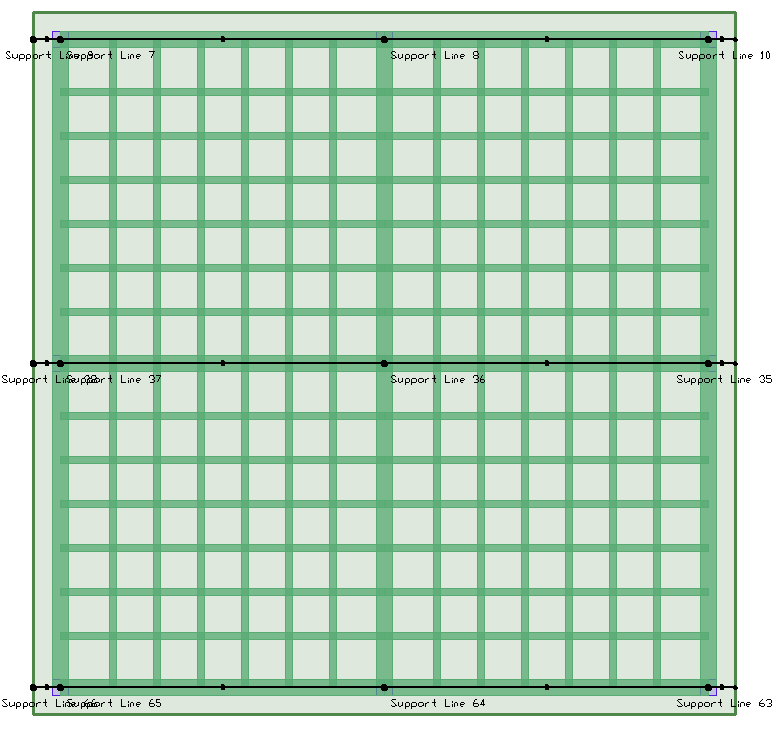
In the images below we can see the support lines needed to design the beams in the model for a regular floor system. Note that each beam has a support line defined to it.
X-direction Support Lines:
Click on image to enlarge it
Y-direction Support Lines:
Click on image to enlarge it
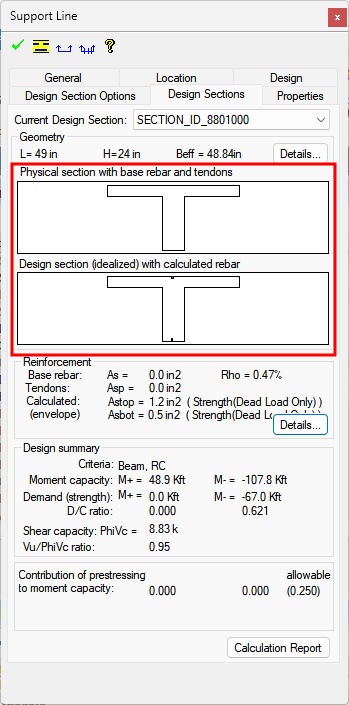
Once the support lines are laid out the user can Generate the Design Sections and then Design the Design Sections. The program will design longitudinal and shear reinforcement for each beam containing a support line. The physical and idealized sections shown in the support line properties design section tab will be similar, showing a T-section for both, as no design section crosses over more than one beam.
Click on image to enlarge it
Layout of Support lines for Waffle/Joist Construction:
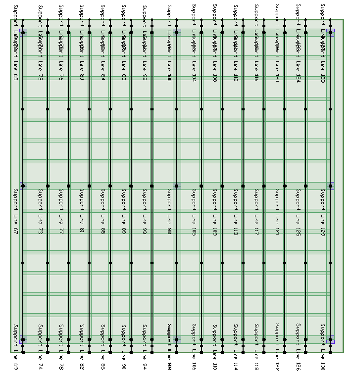
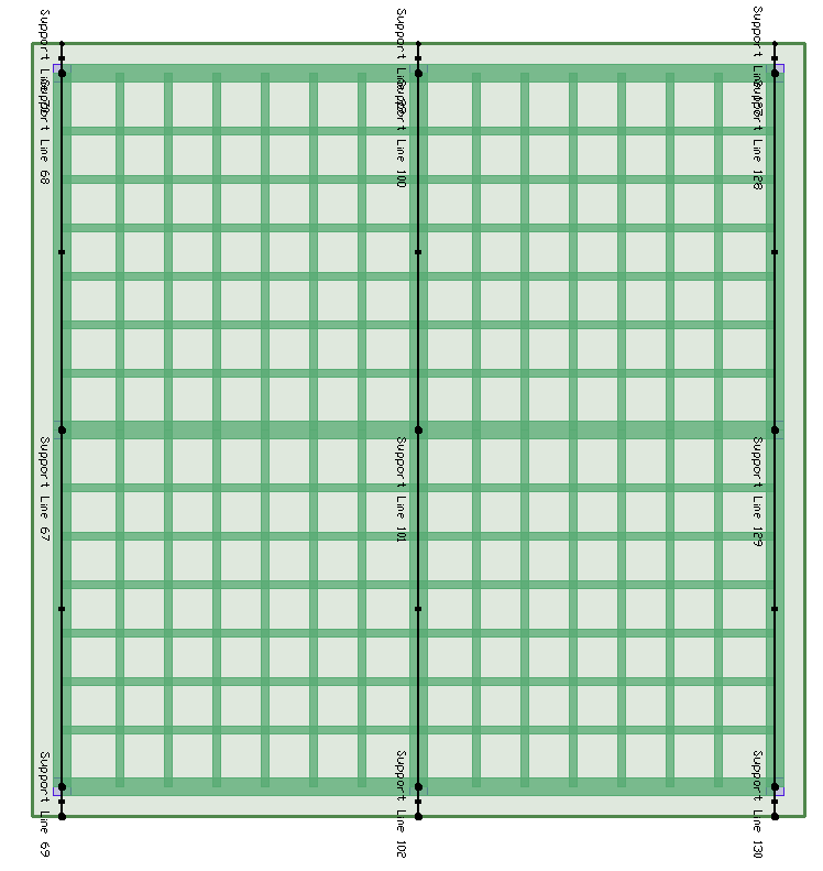
Using the Waffle/Joist Construction option the user can add support lines to the main girders. The design sections for the girder support line will cut over the rib beams and the ribs will be included in the idealized design section. Support lines can be added to the beam using the Dynamic Editor or Manually. The images below show the support lines needed to design the girder and ribs in the model using the Waflle/Joist Construction option.
X-direction Support Lines:
Click on image to enlarge it
Y-Direction Support Lines:
Click on image to enlarge it
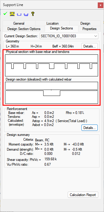
Once the support lines are laid out the user can Generate the Design Sections and then Design the Design Sections. The program will design longitudinal and shear reinforcement for the idealized design section and the reinforcement will have to be split, by the engineer, between the girder and the ribs that are included in the design section. The physical and idealized sections shown in the support line properties design section tab will be different, showing a ribbed section for the physical section and a T-section, with all ribs combined into one stem, for the idealized section.
Click on image to enlarge it
One-Way Shear Results
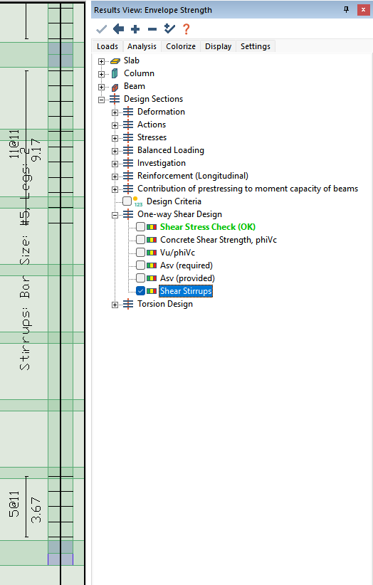
ADAPT-Builder calculates and designs beams for shear. Where the code requires shear reinforcement, ADAPT-Builder will calculate the shear reinforcement to satisfy code minimum reinforcement and ultimate strength provisions. The calculated shear reinforcement can be viewed on screen through the Result Browser by selecting One-Way Shear Design>Shear Stirrups as shown in the image below.
Click on image to enlarge it
One-Way shear results can also be viewed through the Results Browser. The user can view stress check results, along with concrete shear capacity, DC ratio, area of steel required, and area of steel provided.
Note: The user must select a strength combination or the strength envelope combination in the Result Browser Loads tab in order to activate and view One-Way Shear Results from the Analysis tab. For more information see the Result View Panel topic
One-Way Shear section.
Additionally, users can created a Detailed Calculation report for the shear calculation of any design section.
To open the detailed shear calculation report:
-
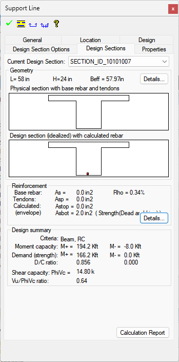
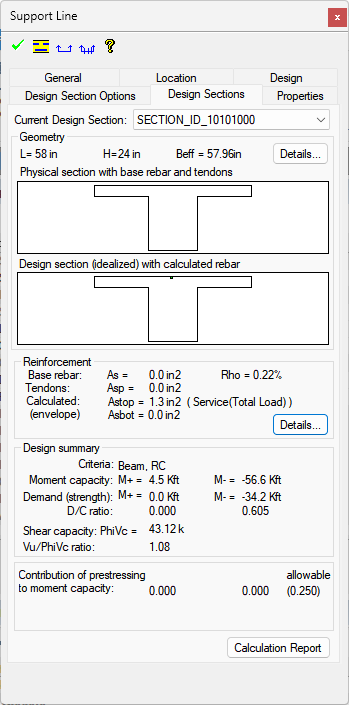
Double click the design section you want to open the detailed report for. This will open the support line properties dialog to the design section tab as shown below.
Click on image to enlarge it
-
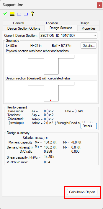
Click on the Calculation Report button at the lower right of the support line properties window design section tab.
Click on image to enlarge it
-
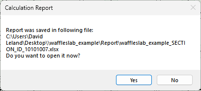
The program will prompt the user with the location of the XLS file created. Click Yes on the Calculation Report dialog to open the XLS report. Clicking No will still save the report in the specified folder however, the report will not be opened.
Click on image to enlarge it
-
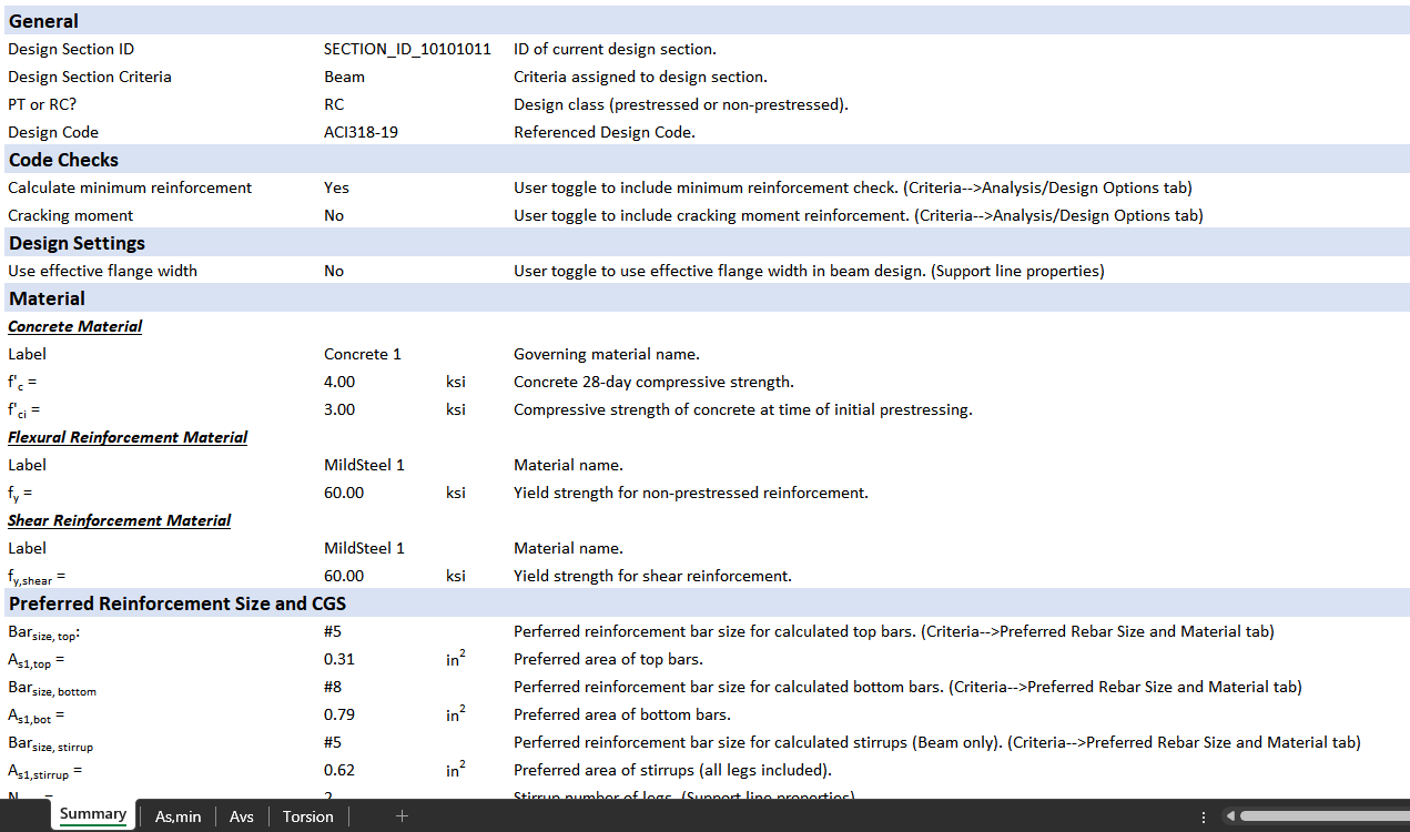
Opening the detailed calculation XLS file will open the file in your default spreadsheet editor to the Summary tab of the spreadsheet.
Click on image to enlarge it
-
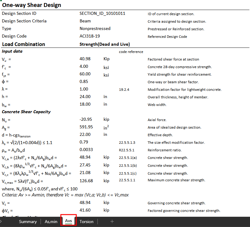
Click on the Avs sheet in order to see the detailed one-way shear calculations for the design section.
Click on image to enlarge it
-
For more information on the equations used for one-way shear, please refer to the Technical Note section of this help file to locate and open the Code Implementation technical note for the design code used in the model.
Torsion Results
ADAPT-Builder includes the option to design beams and one-way slabs for torsional effects. By default, ADAPT-Builder will calculate the torsion in beams and one-way slabs and design reinforcement to resist torsion if the torsional threshold is exceeded.
To initiate threshold checks and design for torsion:
-
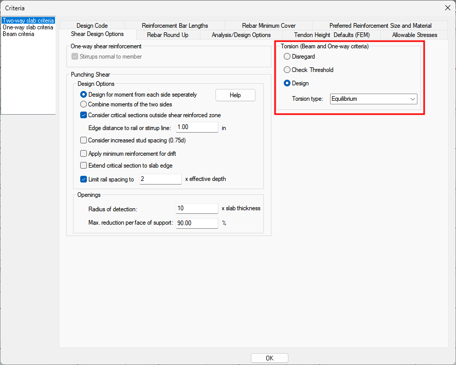
Go to Criteria>Shear Design Options to open the Criteria window to the Shear Design Options tab. The torsion design options are shown marked in red in the image below. For information on the options available please refer to the Criteria:Shear Design Options help topic.
Click on image to enlarge it
-
Choose the Design option to design beams and one-way slabs for torsion during the section design.
-
Click on the Torsion Type drop down and choose the method you would like to use to design the beams and one-way slabs for torsion.
-
Design the Design Sections in the model.
Once the design sections are designed the user can view the results for torsion design through the Results View panel. The user can view Threshold/Stress Check results, along with threshold torsion (phi*Tsh), Tu/phi*Tsh ratio, Design Torsion (Tu), area of shear steel (At/s) required, area of longitudinal steel required (AL/s) and total area of transverse reinforcement (Av+t/s) required.
Note: The user must select a strength combination or the strength envelope combination in the Result Browser Loads tab in order to activate and view Torsion Results from the Analysis tab. For more information see the Result View Panel topic
Torsion section.
Additionally, users can created a Detailed Calculation report for the torsion calculation of any design section.
To open the detailed torsion calculation report:
-
Double click the design section you want to open the detailed report for. This will open the support line properties dialog to the design section tab as shown below.
Click on image to enlarge it
-
Click on the Calculation Report button at the lower right of the support line properties window design section tab.
Click on image to enlarge it
-
The program will prompt the user with the location of the XLS file created. Click Yes on the Calculation Report dialog to open the XLS report. Clicking No will still save the report in the specified folder however, the report will not be opened.
Click on image to enlarge it
-
Opening the detailed calculation XLS file will open the file in your default spreadsheet editor to the Summary tab of the spreadsheet.
Click on image to enlarge it
-
Click on the Torsion sheet in order to see the detailed torsion calculations for the design section.
Click on image to enlarge it
Beam Reinforcement
Once the design is complete the user can view longitudinal reinforcement as well as shear reinforcement calculated for the beam. Longitudinal reinforcement in a beam is generated the same as in slabs and can be viewed on plan after generating the calculated reinforcement plan. Shear reinforcement can be viewed through the One-Way Shear results of the Results View panel. In addition to these methods of viewing the reinforcement the user can show an elevation of the beam including both longitudinal and shear reinforcement.
To create an elevation cut of a beam with longitudinal and shear reinforcement:
-
After Designing the Sections in the model, the first step to create the beam elevation is to Generate the Calculated Rebar Plan for the level you are designing.
-
Once the rebar is shown on plan, double click the beam support line you would like to create an elevation for. This will bring up the support line properties window for the support line clicked on similar to that shown below.
Click on image to enlarge it
-
Click on the Elevation Cut icon in the upper left of the support line properties.
-
The message bar will prompt you to input an insertion point for the elevation cut. Move to white space in the model space and left-click to place the insertion point for the elevation cut. The program will draw an elevation of the beam with longitudinal and shear reinforcement at the location you clicked.
Click on image to enlarge it
-
The elevation cut is created to scale and can be exported to DWG/DXF using the DWG/DXF Export tool of the software.
-
To remove the elevation cut, select the pink X and click the delete key on your keyboard.