Calculated Reinforcement
During the design procedure the program will calculate additional reinforcement at each design section along the support line to bring the section into code compliance for minimum reinforcement and moment capacity. This reinforcement is known as Calculated Reinforcement within ADAPT-Builder. Calculated reinforcement is reported in the Design Strip reports of the Reports Ribbon and within the Design Section tab of the Support Line properties dialog. The program can also generate a plan view of the calculated reinforcement for each load combination after you complete the design of your structural model. Please refer to the Code Implementation section of the Technical Notes help page for Technical Notes containing details on the code provisions implemented and checked by the software per the selected design code.
To generate a calculated rebar plan:
-
Go to Floor Design>Rebar>Calculated Rebar Plan
-
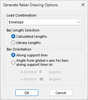
The Generate Rebar Drawing Options dialog window shown below opens.
-
From the drop-down list select the Load Case or Envelope Case for which you would like to display the calculated reinforcement.
-
Select if the displayed bar length will be equal to the Calculated Length or chosen from the Library Lengths that you previously defined in the Criteria: Rebar Lengths tab of the Criteria menu.
-
Set the Bar Orientation option which best suits your needs.
-
Click OK.
-
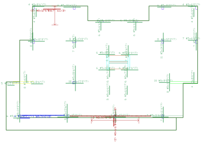
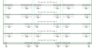
The program displays a plan similar to that shown below, with the reinforcement displayed according to the program’s default settings.
Click on image to enlarge it
-
Use the Visibility Panel to turn on and off rebar calculated reinforcement based on its location within the concrete fiber as well as direction of support line the reinforcement is calculated for.
-
You can export these drawings in DWG or DXF format using the Export to DWG File option of the File ribbon.
Calculated Reinforcement Cover
Calculated reinforcement covers are determined by user inputs in the Criteria: Rebar Cover tab and Preferred Reinforcement Size and Material tab of the Criteria window, as well as the outer and inner layer tag of the support line's properties. Once the support lines have been designated by the user as an outer or inner layer support line, the clear cover is entered by the user in the Criteria: Rebar Cover tab of the Criteria window. The program will calculate the cover to CGS of both the outer layer bar and the inner layer bar automatically based on the bar diameter set in the Criteria: Preferred Reinforcement Size and Material tab and clear cover to the reinforcement. The distance to CGS for the outer layer is clear cover + 0.5* dia. of rebar. The distance to CGS of the inner layer is clear cover + 1.5*dia. of rebar. The user has the ability to use different diameter bars for bottom and top bars but not the inner and outer layer.
Calculated Reinforcement Lengths
Reinforcement lengths are calculated such that the reinforcement is drawn between two sections where rebar demand exists and then extends to the 1st section with no demand at either end of the bar. The program then goes into the curtailment checks in the Criteria - Rebar Length tab of the criteria menu in the following order.
-
The program will round up the bar length based on the settings in the Criteria - Rebar Round Up dialog window. Spacing of bars will also be rounded down at this time.
-
The program will increase the bar length, to the cutoff length setting in the Criteria - Reinforcement Bar Lengths tab of the Criteria dialog, if the bar length does not meet the minimum length specified.
-
The program will then extend rebar due to strength to be beyond the point of zero moment by the distance set in the Extension of strength reinforcement beyond the point of zero moment setting in the Criteria - Reinforcement Bar Lengths tab of the Criteria dialog. .
-
The program will then center the bar by adding length to the shorter side over the column or within the midspan based on the option to center reinforcement over the column or in midspan in the Criteria - Reinforcement Bar Lengths tab of the Criteria dialog.
Note: If any of the settings above are not selected to be used or are set to 0 the setting will be ignored and no extension will occur for that specific setting.
Calculated Beam Reinforcement
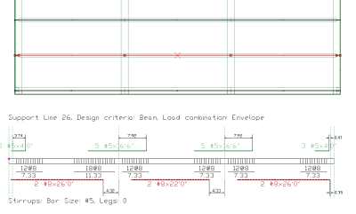
Longitudinal reinforcement in beams can be generated and shown on plan similar to longitudinal reinforcement within the slabs with the difference that the bottom bars are referenced from the bottom of the beam. One-way shear reinforcement within slabs and beams is automatically calculated by the program and can be displayed graphically along support lines using the Results View panel. Both calculated longitudinal and shear reinforcement of beams can also be displayed in an elevation cut of the support line as well.
 To view one-way shear reinforcement along support lines:
-
Analyze the model.
-
Design the Design Sections.
-
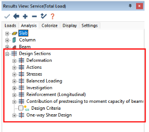
Go to the Results View panel Analysis tab and expand the Design Section tree.
Click on image to enlarge it
-
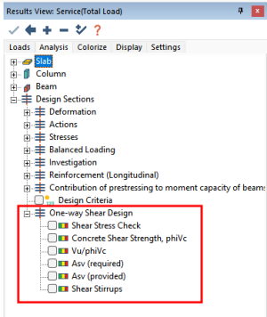
Expand the One-way Shear Design tree.
Click on image to enlarge it
-
Check the box to the left of Shear Stirrups.
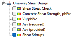
The shear stirrup graphic will be displayed along the support lines as shown in the image below.
Click on image to enlarge it
For detailed information on the equations used to calculate the longitudinal and shear reinforcement of beams, please refer to the Technical Note: Code Implementation section of this help file for the design code you are using.
Design Section Reinforcement Details
Users can view details about the calculated reinforcement provided by the program using the Support Line properties Design Section tab. Within the Design Section tab of the support line properties users can see the area of calculated reinforcement for each design section along the support line for the top and bottom bars. In addition the governing load combination will be called out as well. Clicking on the Details button in the reinforcement section of the Support Line properties Design Section tab wil give the user precise information about the location of the rebar within the section elevation.
 To view reinforcement details for the design section:
-
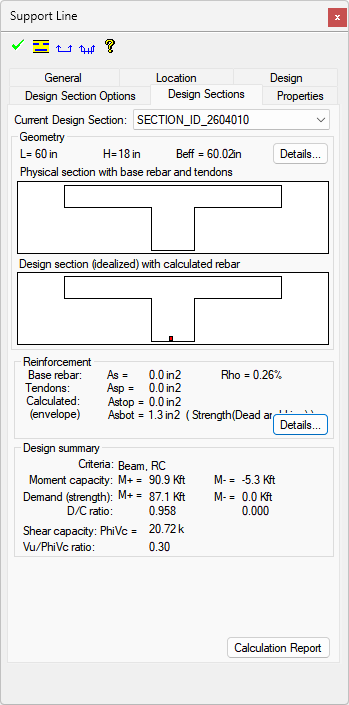
Double click the design section you want to view details from. This will open the Support Line properties window to the Design Section tab as shown below.
-
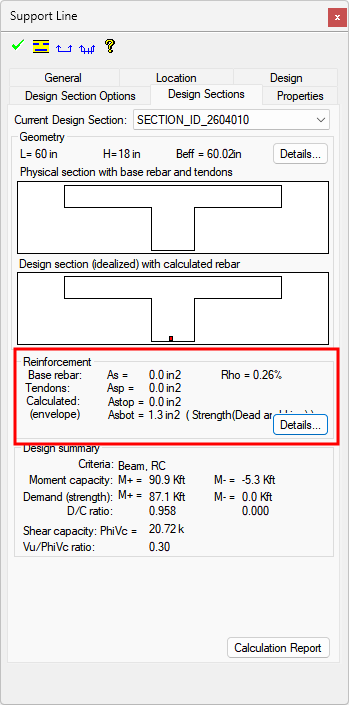
In the Reinforcement section of the support line properties design section tab you can view the area of Base Reinforcement, Tendons, and Calculated Reinforcement within the design section..
-
Note that to the right of the Area of steel for Top and Bottom reinforcement the controlling load combination will be displayed.

-
Click on the Details button within the Reinforcement section.

-
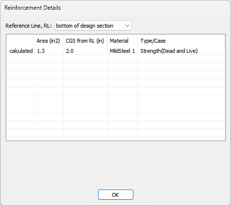
The Reinforcement Details window will open showing detailed information about the location and amount of reinforcement within the design section.
